Headlight lens resurfacing apparatus and method

a headlight lens and resurfacing technology, which is applied in the field of resurfacing of transparent plastic surfaces, can solve the problems of becoming cloudy, saving both the cost of new lenses and the cost of replacement labor, and achieve the effects of saving both the cost of new lenses and replacement labor, restoring optical clarity and light output, and being more cost-effectiv

Inactive Publication Date: 2008-07-29
KUTA TERRY MITCHELL
View PDF18 Cites 23 Cited by
  • Summary
  • Abstract
  • Description
  • Claims
  • Application Information

AI Technical Summary

Benefits of technology

[0010]The present invention teaches an alternative to replacement that is more cost effective, in that it does not require removal of worn lenses nor mounting of new ones. Thus, this approach saves both the cost of new lenses as well as the cost of labor for replacement. The present invention teaches an apparatus that is ideally suited to removing the outer damaged surface of on an existing lens and a method for doing so. Therefore, the present invention method removes the abraded surface on a lens while it is still mounted on the vehicle, and restores optical clarity and light output to the level of new lenses.
[0011]The present invention teaches the refinishing of an exterior automotive lens having a damaged exterior surface in situ using a continuous movement and oscillating motion, with first, a 320 grit sanding disc, next a 600 grit sanding disc and finally a 1500 grit sanding disc while flushing the surface with water to prevent melting of the surface. This is followed by buffing the surface with a polishing compound until a high gloss is achieved. Finally, the surface is coating with a transparent ultraviolet hardenable coating material, which is then hardened by exposure to an ultraviolet light source. This method is accomplished using an oscillating tool having a remotely located drive so as to avoid mixing an electric drive with the water used for flushing the operation.

Problems solved by technology

Such lenses are quite clear, tough and chemical resistant, but suffer from surface crazing due to scratches that cause them to become cloudy over time, primarily through normal mechanical abrasion in use.
However, this is expensive because of the cost of new lenses and also because of the high hourly pay rate for mechanics that remove the worn lenses and replace them with new ones.
Thus, this approach saves both the cost of new lenses as well as the cost of labor for replacement.

Method used


Image

  • Headlight lens resurfacing apparatus and method
  • Headlight lens resurfacing apparatus and method
  • Headlight lens resurfacing apparatus and method

Examples


Embodiment Construction

[0022]The above described drawing figures illustrate the invention in at least one of its preferred embodiments, which is further defined in detail in the following description. Those having ordinary skill in the art may be able to make alterations and modifications in the present invention without departing from its spirit and scope. Therefore, it must be understood that the illustrated embodiments have been set forth only for the purposes of example and that they should not be taken as limiting the invention as defined in the following.

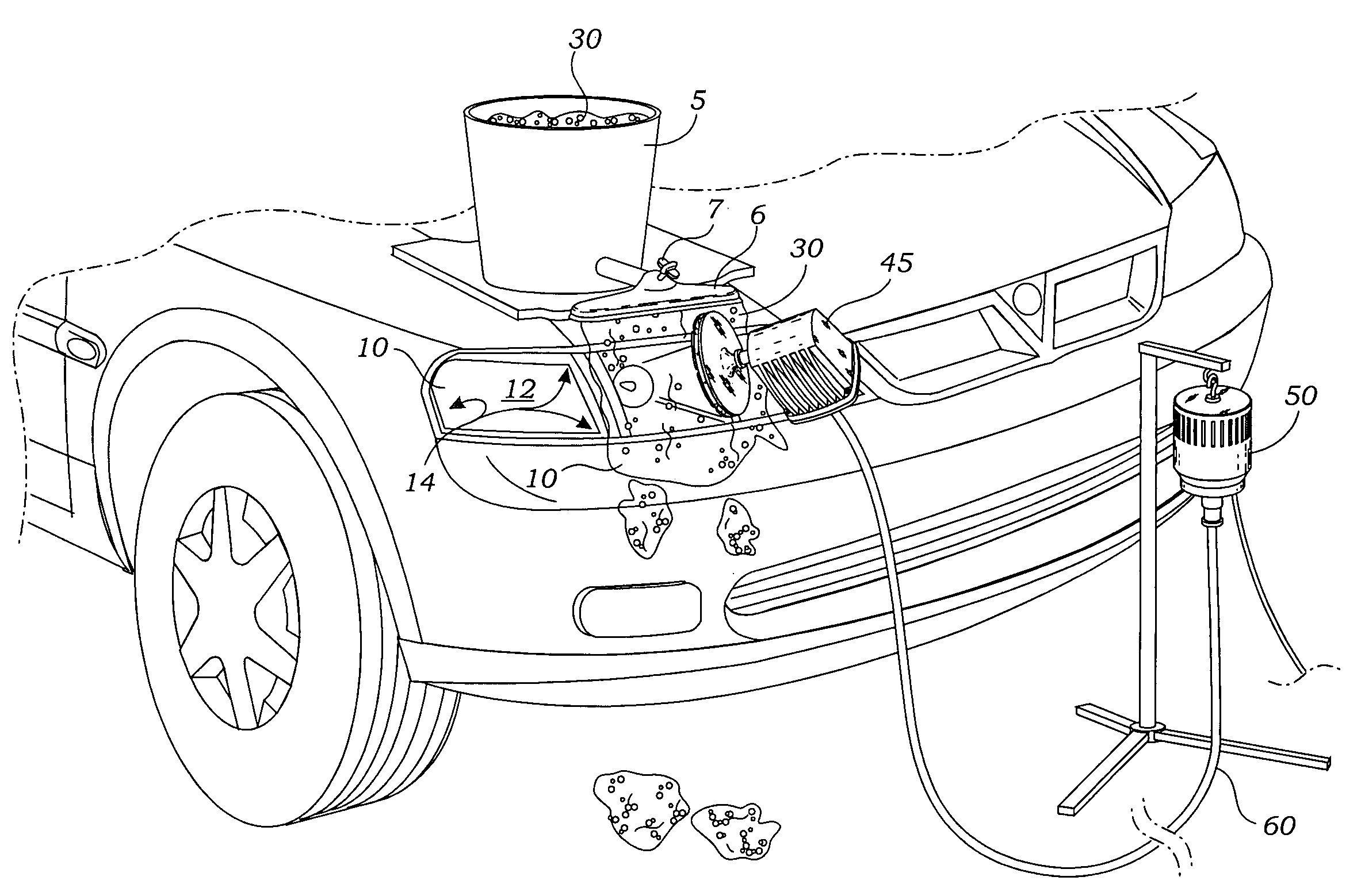
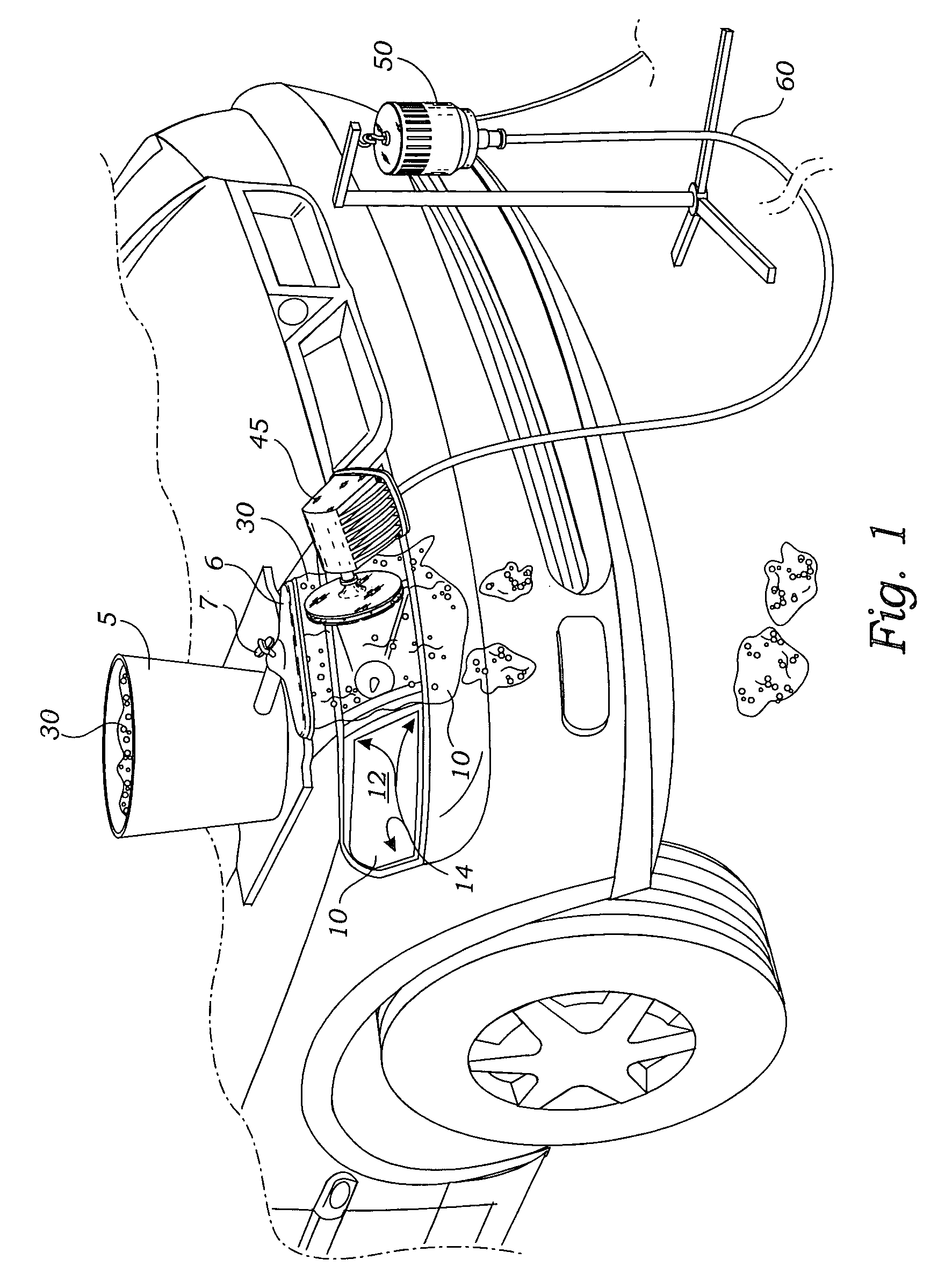
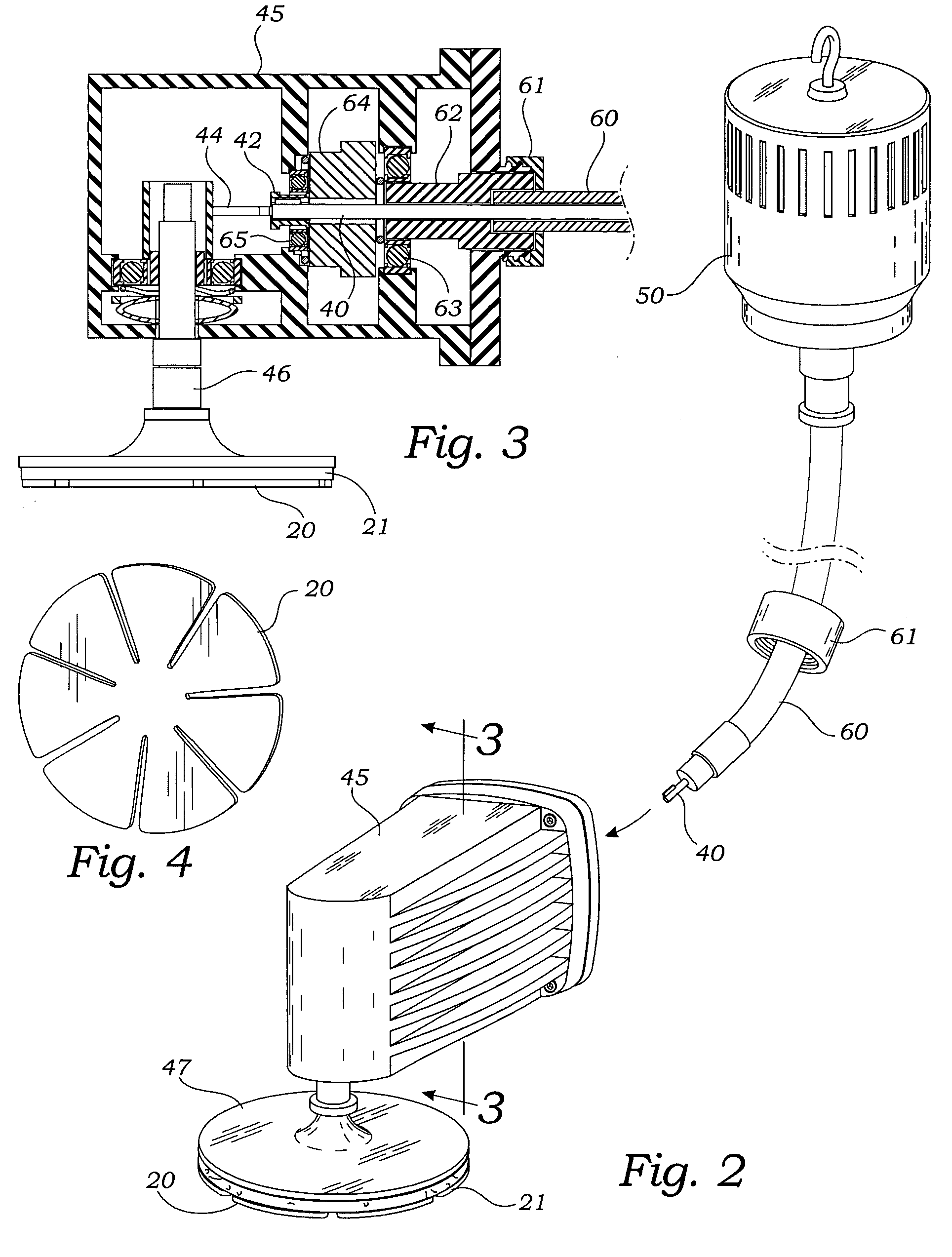
[0023]The present invention is an apparatus and method for refinishing the outer surface of automotive lenses 10 in situ, that is, without removing them from the automobile, as shown in FIG. 1. The lenses 10 have a damaged exterior surface 12, primarily crazing of the surface, caused by the impact of stones and sand in the roadway, ultra-violet damage from the Sun and chemical damage from the environment, including acid rain, roadway chemicals and s...


PUM

PropertyMeasurementUnit
particle sizeaaaaaaaaaa
transparentaaaaaaaaaa
thermal stress breakageaaaaaaaaaa

Abstract

Refinishing an exterior automotive lens having a damaged exterior surface in situ using a continuous movement and oscillating motion, with first, a 320 grit sanding disc, next a 600 grit sanding disc and finally a 1500 grit sanding pad while flushing the surface with water to prevent melting of the surface. Buffing the surface with a polishing compound until a high gloss is achieved. Finally, coating the surface with a transparent ultraviolet hardenable coating material, and hardening it by exposure to an ultraviolet light source. This method is accomplished using an oscillating tool having a remotely located drive.

Description

BACKGROUND OF THE INVENTIONIncorporation by Reference[0001]Applicant(s) hereby incorporate herein by reference, any and all U.S. patents and U.S. patent applications cited or referred to in this application.Field of the Invention[0002]This invention relates generally to resurfacing of transparent plastic surfaces due to wear and crazing, and more particular to a specific apparatus singly adapted for such resurfacing and a method of using the apparatus.Description of Related Art[0003]The following art defines the present state of this field:[0004]Coburn, et al., U.S. Pat. No. 5,027,560 teaches a machine for finishing the surface of a lens including a lap holder moved orbitally in a first plane, a lens arm support having a lens holder, the lens arm support being oscillated in a second plane perpendicular to the first plane, the lens arm holder being also simultaneously oscillated in a third plane perpendicular to the first plane, the lens holder being urged toward the lap holder.[0005...

Claims


Application Information

Patent Timeline
Patent Type & Authority Patents(United States)
IPC IPC(8): B05D3/06B05D3/10B05D3/12B24B1/04G02B1/12B05D5/06B29C73/00B29C73/24
CPCB29C73/00B29C73/24B29L2031/3055B29C2073/262
Inventor KUTA, TERRY MITCHELL
Owner KUTA TERRY MITCHELL
Why Eureka
Try Eureka