Vacuum cleaner
A vacuum cleaner and electric technology, applied in vacuum cleaners, cleaning equipment, household appliances, etc., can solve the problems of high noise, noise impact, and low efficiency, and achieve the effects of reducing exhaust sound, high suction performance, and reducing noise
- Summary
- Abstract
- Description
- Claims
- Application Information
AI Technical Summary
Problems solved by technology
Method used
Image
Examples
Embodiment 1
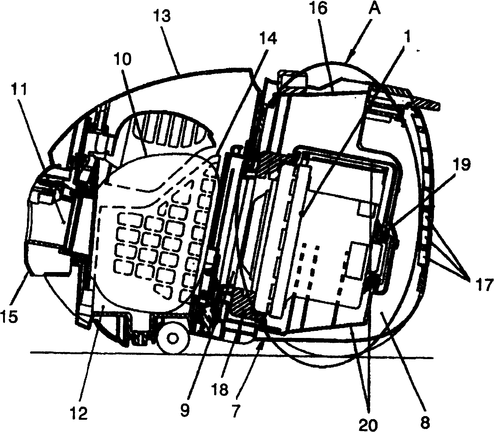
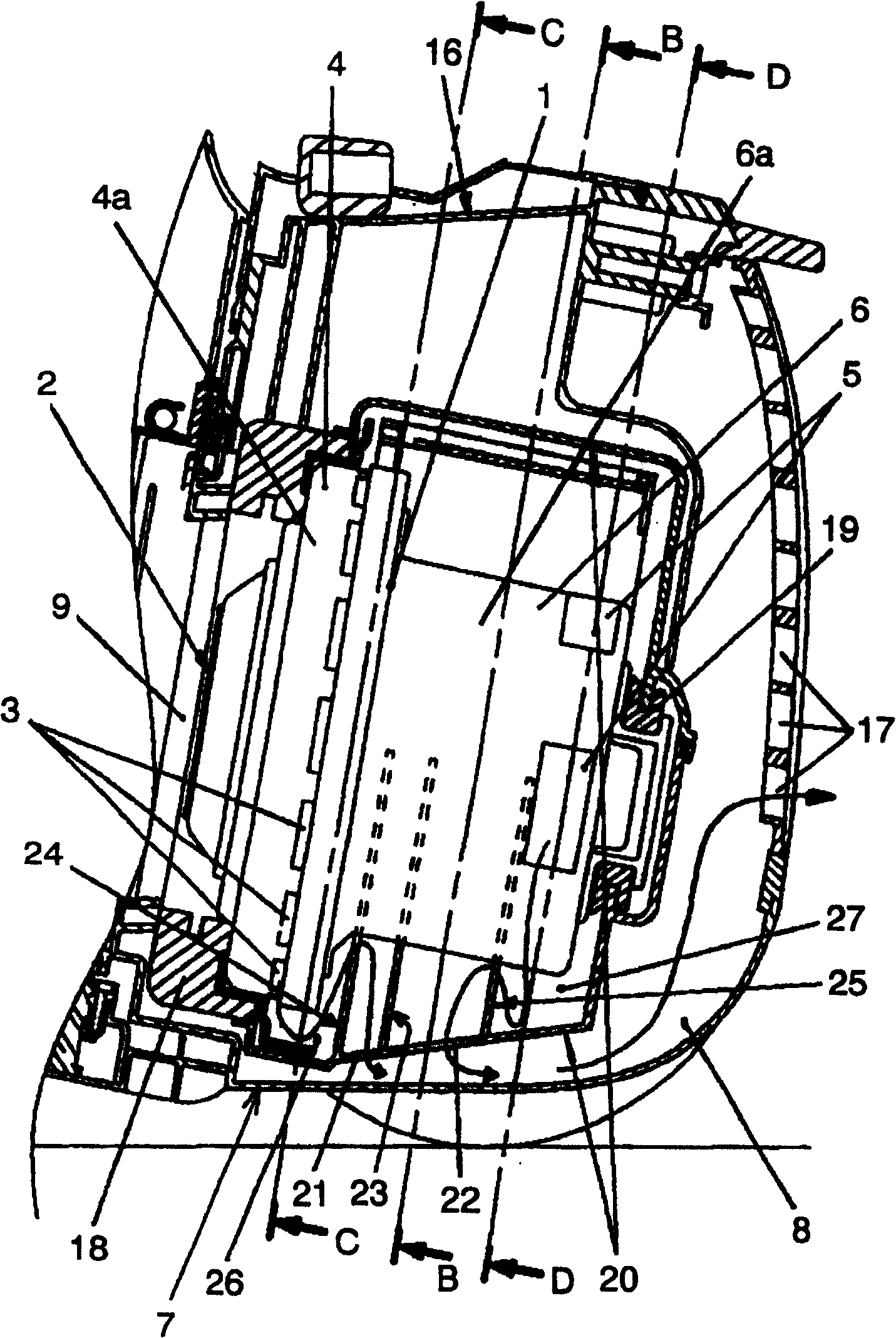
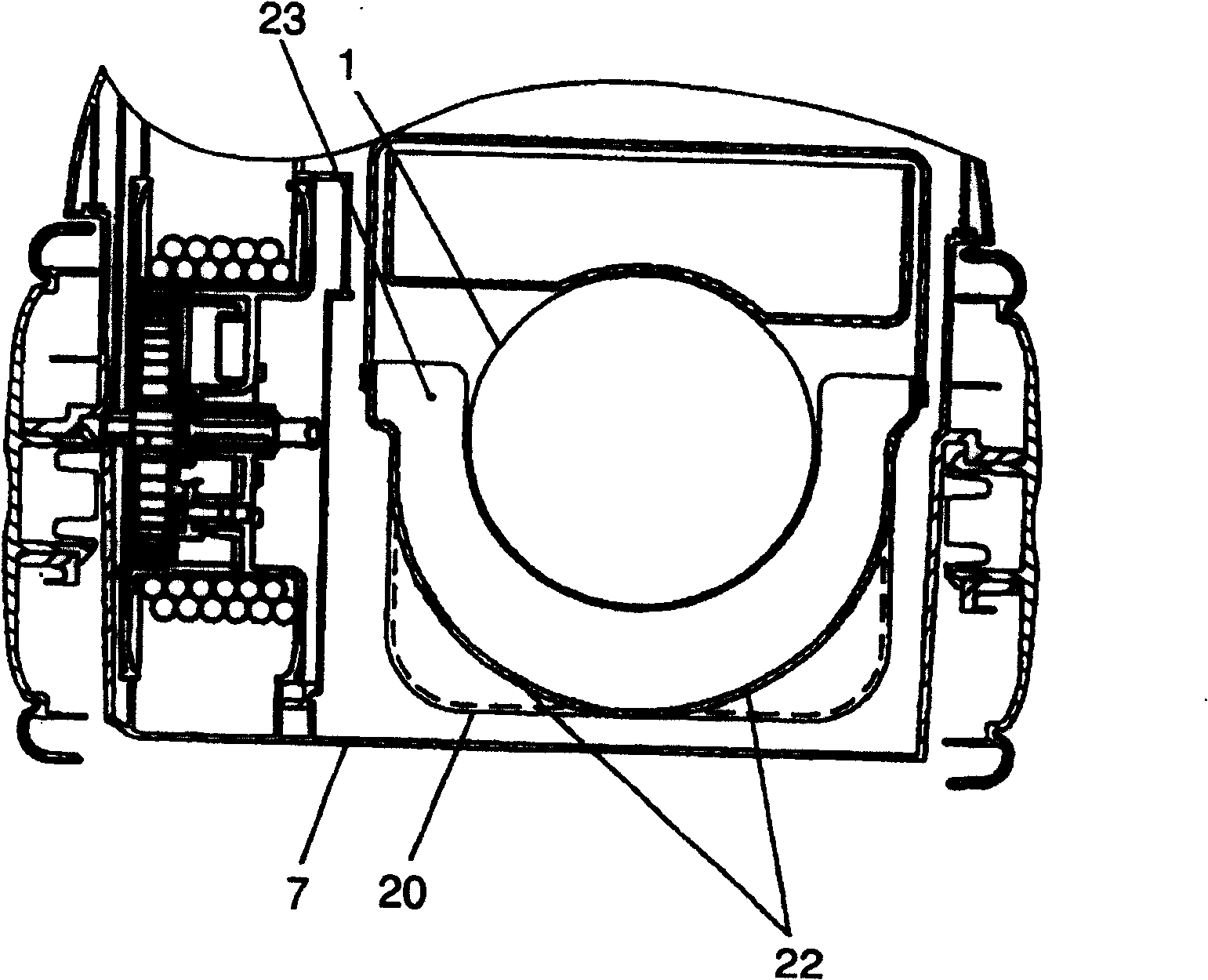
[0044] Refer below Figure 1 to Figure 5 The first embodiment of the present invention will be described.
[0045] figure 1 , figure 2 Among them, the electric blower 1 that generates suction wind includes a fan part 4 and a motor part 6. The fan part 4 is composed of an impeller (not shown) that generates wind by rotation, an air inlet 2 for sucking air, and a housing 4a that covers the impeller. and the first exhaust port 3 that discharges the wind generated by the impeller to the outside. The motor part 6 houses the rotational power of the impeller, that is, the motor, and is arranged on the bracket 6a that covers the motor and drives the impeller to the outside. The second exhaust port 5 through which the generated air is discharged to the outside is constituted. 7 is an electric vacuum cleaner body, the electric blower chamber 8 in which the electric blower 1 is arranged, the suction port 9 communicating with the suction port 2 on the upstream side of the suction por...
Embodiment 2
[0063] Refer below Figure 6 ~ Figure 12 A second embodiment of the present invention will be described.
[0064] Image 6 , Figure 7 Among them, the electric blower 111 that generates suction wind is composed of an air inlet 112, a fan unit 114 having first exhaust ports 113 arranged at regular intervals, and a motor unit 116 that generates rotational power and has second exhaust ports 115. constitute. 117 is an electric vacuum cleaner body, the electric blower chamber 118 in which the electric blower 111 is configured, the suction port 119 communicating with the suction port 112 on the upstream side of the suction port 112 of the electric blower 111, and the paper bag 120 for collecting dust are arranged. A suction device (not shown) for sucking dust on the upstream side of the paper bag 120 and a dust collection chamber 122 having a suction port 121 communicating with the paper bag 120 are constituted. Above the dust collecting chamber 122 is formed a dust collecting c...
Embodiment 3
[0081] refer to Figure 13 , Figure 14 A third embodiment of the present invention will be described. In addition, the same code|symbol is attached|subjected to the same part as the above-mentioned embodiment, and the description is abbreviate|omitted.
[0082] On the outer rear side of the outlet 132 provided in the lower muffler box 130b, there is provided a detour wall 144 formed in a substantially arc shape with a convex front end on the side of the outlet 132 of the lower muffler box 130b. At the rear of the detour wall 144 , a sound absorbing material 145 is fixed along the wall surface of the detour wall 144 .
[0083] Next, the operation and function of the electric vacuum cleaner constructed as above will be described.
[0084] Since the exhaust gas flowing out of the muffler box 130 flows smoothly along the substantially arc-shaped detour wall 144, there is no loss of exhaust air and high suction performance can be maintained. Moreover, the exhaust air is bent by...
PUM
 Abstract
Description
Claims
Application Information
 - R&D
- Intellectual Property
- Life Sciences
- Materials
- Tech Scout
- Unparalleled Data Quality
- Higher Quality Content
- 60% Fewer Hallucinations
Browse by: Latest US Patents, China's latest patents, Technical Efficacy Thesaurus, Application Domain, Technology Topic, Popular Technical Reports.
© 2025 PatSnap. All rights reserved.Legal|Privacy policy|Modern Slavery Act Transparency Statement|Sitemap|About US| Contact US: help@patsnap.com


