Level measurement apparatus

Pending Publication Date: 2022-09-22
JOHNSON MATTHEY PLC
View PDF0 Cites 0 Cited by
  • Summary
  • Abstract
  • Description
  • Claims
  • Application Information

AI Technical Summary

Benefits of technology

[0019]In order to increase the pressure rating of the windows they may be mounted in the wall of the enclosure via a tapered seal, in the form of a sloped or stepped wall seal, to prevent the windows from being pushed into the apparatus when subjected to pressure from the material phases within the vessel in which the apparatus is disposed. In certain configurations, the enclosure wall is metallic, the one or more windows are glass, and the one or more glass windows are mounted in the metallic wall of the enclosure via a glass-metal bond. Sight glasses, such as borosilicate sight glasses, are available which are pr

Problems solved by technology

As such, the apparatus doesn't have the limitations of traditional guided wave radar solutions in which the electromagnetic radiation is directed dow

Method used


Image

  • Level measurement apparatus
  • Level measurement apparatus
  • Level measurement apparatus

Examples


Example

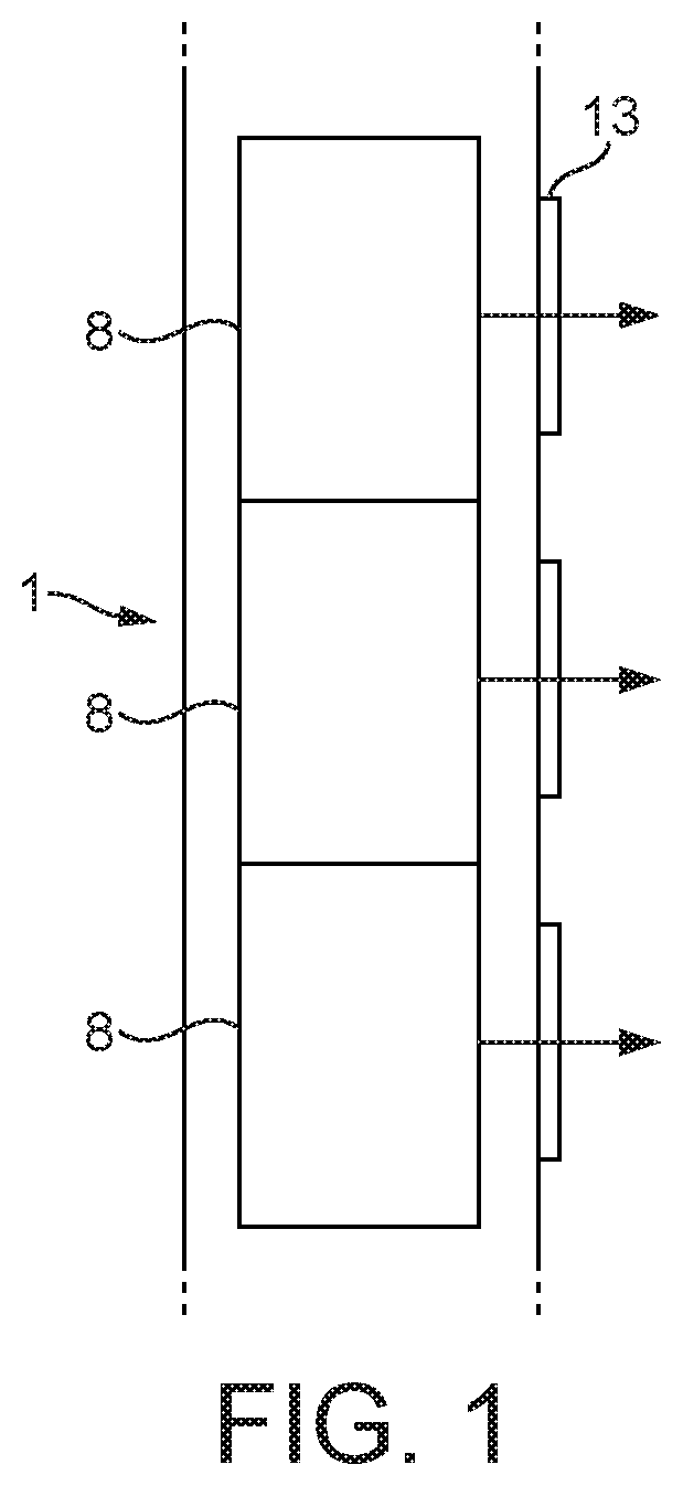
[0030]FIG. 1 depicts a schematic cross-sectional view of a level measurement apparatus comprising a plurality of microwave transceivers 8 within an enclosure 12. Also depicted are windows 13 which are located to allow electromagnetic radiation to pass out of and back into the enclosure 12. When used in fluid environments the enclosure 12 may be a dip tube or dip pipe that provides a mechanical and chemical resistant barrier between the microwave transceivers and the materials being profiled. The material of the enclosure is chosen to have sufficient strength and chemical resistance.

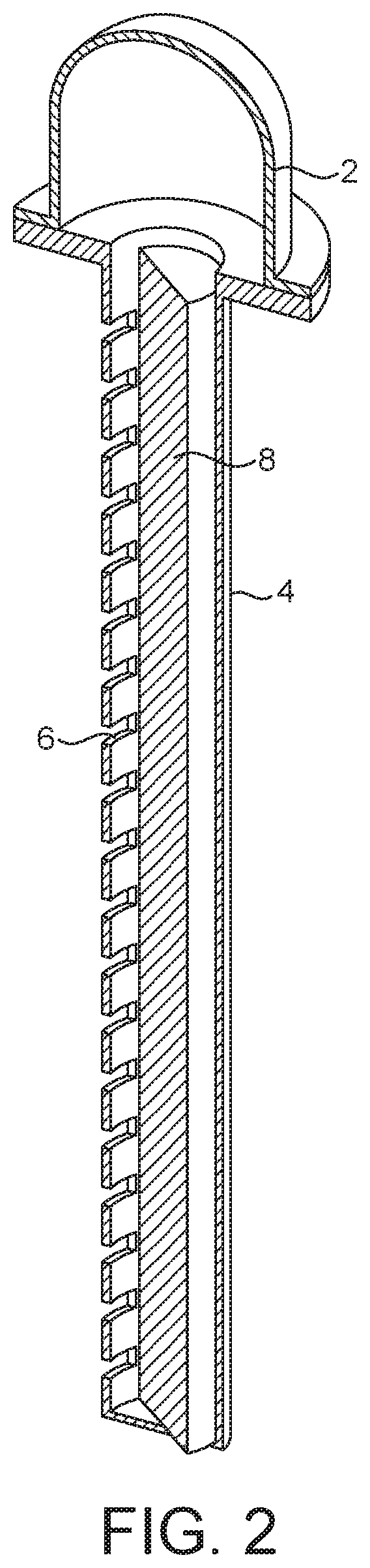
[0031]In the arrangement shown in FIG. 1, each window 13 is associated with a corresponding microwave transceiver 8. FIG. 2 shows an alternative arrangement which has a microwave transceiver in a housing 2 and an elongate probe portion 4 which extends into the vessel and contents in use. The probe portion 4 comprises an elongate cylindrical microwave wave guide defined by a conductive wave guide wall. The...


PUM


Abstract

An apparatus for determining the identity, location or level of one or more material phases or the location of an interface between two material phases within a vessel, the apparatus having a transmitter for transmitting an electromagnetic transmission signal, a receiver for receiving an electromagnetic return signal, and an enclosure configured to be at least partially submerged within the one or more material phases in the vessel, the enclosure comprising a wall defining an interior and an exterior of the apparatus to seal the apparatus from ingress of the one or more material phases into the apparatus when submerged within the one or more material phases in the vessel, the enclosure wall being non-transparent to the electromagnetic transmission signal.

Description

FIELD[0001]The present invention relates to an apparatus for determining the identity, location or level of one or more material phases or the location of an interface between two material phases within a vessel such as an oil separator unit.BACKGROUND[0002]The measurement of levels of fill, particularly of fluids including liquids, gases and multi-phase materials such as emulsions and slurries, has been carried out for many years using nucleonic level gauges, by measuring the amount of radiation emitted by a radiation-source which is detected at one or more levels within the vessel. The radiation is attenuated as is passes through materials, the amounts of attenuation being related to the density of the materials between a source and a detector. By comparing the attenuation of radiation detected at different levels of the vessel, it is possible to estimate the height of materials contained in the vessel.[0003]A density profiler based on these principles has been described in WO2000...

Claims


Application Information

Patent Timeline
IPC IPC(8): G01F23/284G01F23/04H01Q1/22G01N33/28
CPCG01F23/284G01F23/04H01Q1/225G01N33/2847G01F23/2845G01S13/88G01S7/41G01N22/00G01N33/28
Inventor BARKER, GRAHAMBECKETT, OLIVER JOHNTIPTON, CARL
Owner JOHNSON MATTHEY PLC
Why Eureka
Try Eureka