
Asynchronous persistency of replicated data changes in a database accelerator

a database accelerator and replication technology, applied in the field of database crash recovery, can solve the problems of inability to recover inability to maintain large amounts of data, and inability to meet the requirements of database recovery,

Pending Publication Date: 2022-09-22
IBM CORP
View PDF8 Cites 1 Cited by
  • Summary
  • Abstract
  • Description
  • Claims
  • Application Information

AI Technical Summary

Benefits of technology

The patent describes a method for updating and querying a database without slowing down the system. The method decouples the processing of metadata (such as logging and state storage) from the processing of user data (such as changing the table structure or adding new records). This allows for faster updates and processing of metadata asynchronously. The method also suggests recovery strategies based on the volume of data to be recovered, to minimize the time required for the recovery process. Overall, the method improves the speed and efficiency of database updates and queries.

Problems solved by technology

Managing large amounts of data remains a continuous problem for enterprise IT (information technology) organizations.
However, it turned out that the analytic processing has a too strong and unpredictable influence on the performance of online transaction processing.
However, query data in the target DBMS might be out of date if the loading was performed some time ago and the corresponding source table has been modified in the meantime.
However, guaranteeing ACID properties may cause significant overhead when the source database is modified by current transactions.
In particular, logging slows down processing insert / update / delete (IUD) statements because change records have to be written to a persistent storage medium before transactions can continue.
Compared to the frequently used in-memory processing of changes to the content of the database table, adding this persistence layer using transaction logs is comparatively slow.
However, all of the traditional coupled databases being optimized for transactions on one side, and for analytical processing on the other side, may require the known overhead for maintaining persistent recovery logs which may slow down the processing of the combined databases significantly in addition to a non-optimized usage of the changes from the source database in the target database.
Due to asynchronous writing of committed changes from in-memory data structures to their persistent counterparts, some of them might be missing in the target database system in case of a database crash.
The delay caused by the recovery may be much lower if compared to known solutions, but processing and storage cost for asynchronously maintaining the database snapshot on the target database system may be a little bit higher.
However, this is only a low price for a higher availability and short-term recovery times of the target database system.
However, this type of database is often not optimal for analysis-type of operations.
He may eventually experience a little delay in his analysis query.
However, because the response-time for complex analysis queries is comparably long anyway, the user may not be aware of the delay at all.

Method used


Image

  • Asynchronous persistency of replicated data changes in a database accelerator
  • Asynchronous persistency of replicated data changes in a database accelerator
  • Asynchronous persistency of replicated data changes in a database accelerator

Examples


embodiment 200

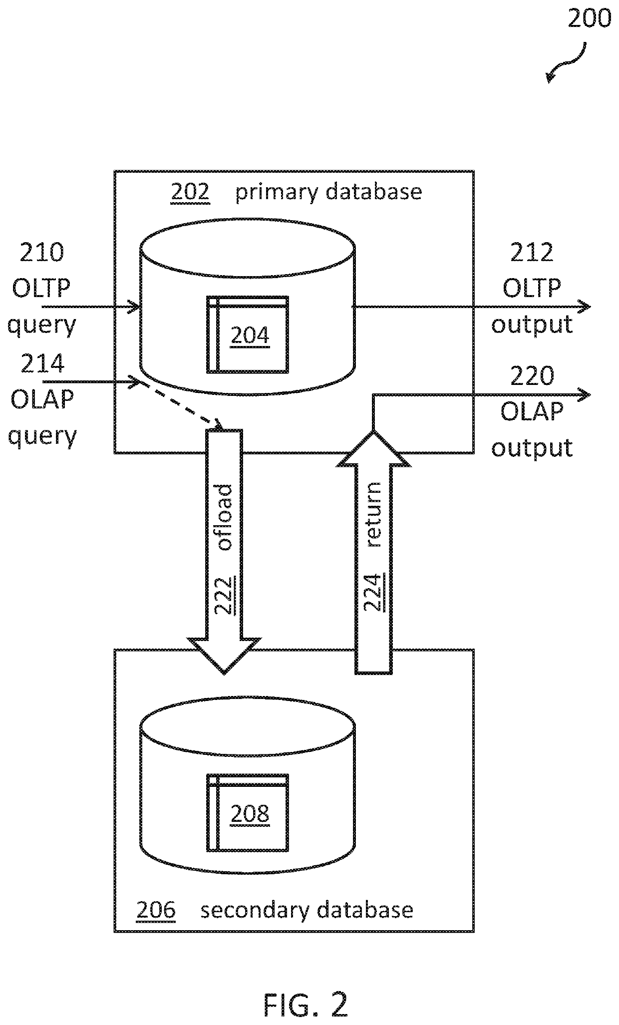
[0073]FIG. 2 shows a block diagram of an embodiment 200 of linked databases. The primary or source database 202 receives OLTP queries 210 and OLAP queries 214. Those queries that are identified as OLAP queries 214 are transferred or offloaded, 222, to the secondary or target database 206. The source database 202 comprises a plurality of tables 204 and related stored data. The target database 206 also comprises tables which represent at least a subset of the database tables 204 of the source database 202 and at least a subset of the data in the database tables 208.

[0074]After the OLAP operation has been performed by the target database 206, the data are returned, 224, and the OLAP output 220 is returned back to the requesting program or process. OLTP queries 210 are executed directly in the source database 202 and returned as OLTP output 212 to the requesting program or process. Hence, the OLTP or source database 202 may operate at its best performance because it is not slowed down b...

embodiment 300

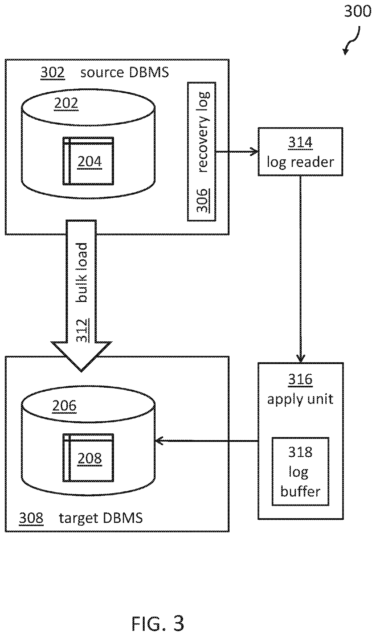
[0076]FIG. 3 shows a block diagram of an embodiment 300 of how the target database can be synchronized. The source database management system 302 controls the operation of the source database 202 and its related tables 204 (compare FIG. 2). The same applies to the target database management system 308 for the target database 206 and the related tables 208.

[0077]The source database management system 302 also maintains the recovery log file 306 for the source database 202. A log reader or log file reader 314 reading the recovery log file 306 provides these data to the applying unit 316 which applies the changes (i.e., insert, update, delete) performed to the source database also to the target database 206 for the selected tables and the selected set of data. The selected tables and the selected set of data may be a subset of those related tables and data in the source database 202 as defined beforehand. The applying unit 316 can optimize the application of the changes to the target da...

embodiment 500

[0085]FIG. 5 shows a block diagram of an embodiment 500 of the linked database system comprising components for a customer priority optimized recovery strategy. The source DBMS 542 has exemplary a first source database 504 of a first user or tenant (e.g., in a cloud computing environment) and a second source database 506 of a second user or tenant. In additional, separated source database systems for other users or tenants may be available.

[0086]Separate data synchronization subsystems 510, 512 are implemented in the data synchronization system 508 in order to synchronize the source databases 504, 506 with the respective in-memory portions 518, 520 of the in-memory target database 516. The query process 522 receives the database queries for execution in the in-memory portion of target database(s) 516. These queries are typically the OLAP queries which have been offloaded from the source database(s) 504, 506.

[0087]The recovery process or processor 524 of the target DBMS 514 also rece...


PUM


Abstract

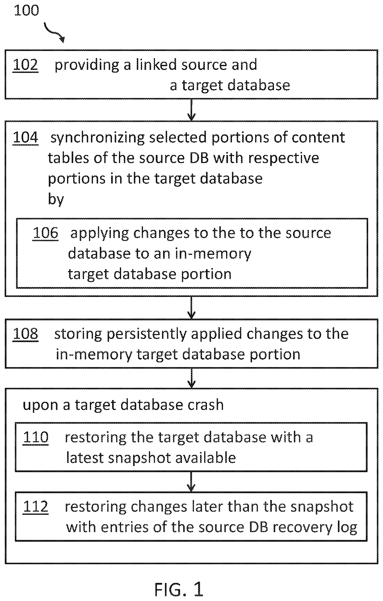
A computer-implemented method for a crash recovery for linked databases may be provided. The linked databases comprise a source and related target database. Selected queries of the source database are transferred to the target database. The method comprises synchronizing selected portions of the source database with tables of an in-memory portion of target database and, storing persistently applied changes to the in-memory target database portion asynchronously and persistently. Upon a database crash of the target database system, the method also comprises restoring, the in-memory target database portion with the latest snapshot available, and applying, changes from the source database recovery log file that have a later timestamp than the latest snapshot available in the persistent target database storage of the in-memory target database portion.

Description

BACKGROUNDField of the Invention[0001]The invention relates generally to crash recovery for a database, and more specifically, to a computer-implemented method for a crash recovery for linked databases. The invention relates further to a linked database system with crash recovery for linked databases, and a computer program product.Related Art[0002]Managing large amounts of data remains a continuous problem for enterprise IT (information technology) organizations. This is (i) due to the ever-growing amount of data and (ii) also view to the variety of the data. In addition to traditional structured data, also semi-structured and so-called unstructured data are stored in large amounts in enterprise IT systems. Furthermore, in addition to traditional transaction oriented databases, special database systems optimized for analytical processing, have been introduced to satisfy the industry requirement for more and more data analytics. On the other hand, attempts have been made to do all a...

Claims


Application Information

Patent Timeline
Patent Type & Authority Applications(United States)
IPC IPC(8): G06F16/27G06F11/14G06F16/28G06F16/22
CPCG06F16/273G06F11/1446G06F16/284G06F16/221G06F2201/80G06F11/1471G06F11/2094G06F11/2097
Inventor BEIER, FELIXBUTTERSTEIN, DENNISLUECK, EINARPERATHONER-TSCHAFFLER, SABINE
Owner IBM CORP
Learn More