A Device For Determining A Volume Of Gas In A Sample

a gas volume and sample technology, applied in the field of devices for determining the volume of gas in samples, can solve the problems of large size, difficult transportation, and a number of security and toxicity issues

Pending Publication Date: 2022-09-29
TOTALENERGIES SE
View PDF0 Cites 0 Cited by
  • Summary
  • Abstract
  • Description
  • Claims
  • Application Information

AI Technical Summary

Benefits of technology

[0052]The present invention makes it possible to address the need mentioned above. In particular the invention provides for a device for determining a volume of gas in a sample, notably a deriving from the pyrolysis of a hydrocarbon-containing rock sample, which makes it possible to ensure an accurate and safe measurement of the volume of the gas, without such device being cumbersome. The invention also provides a device which allows a complete material balance of a pyrolysis process.
[0053]This is achieved by a device comprising a needle and an analysis compartment comprising a cell fluidically connected to the needle. As the needle comprises a proximal part comprising a lumen, the direct transfer of gas from a vessel to the analysis compartment via the needle is possible without the gas being transferred to intermediate chambers or cells, and therefore without a quantity of a gas being lost or contaminated during the transfer. As a result, the measurement of the volume of gas is directly carried out in the analysis compartment. This accurate measurement of the volume of gas in the analysis compartment, even for very small volumes of gas, makes it possible to carry out a complete material balance.
[0054]Furthermore, as the device according to the invention does not comprise a Toepler pump and therefore does not make use of mercury, the process is safe and there are no toxicity issues.
[0055]Advantageously, the presence of a sheath around the needle, which preferably is movable relative to the needle independently from the frame, makes it possible to transfer the gas from the vessel to the needle and then to the analysis compartment in a gas-tight manner, without any contamination from the external environment.

Problems solved by technology

However, such pump comprises a significant quantity of mercury which may raise a number of security and toxicity issues.
Furthermore, this pump has quite a large size which makes transportation difficult.

Method used


Image

  • A Device For Determining A Volume Of Gas In A Sample
  • A Device For Determining A Volume Of Gas In A Sample
  • A Device For Determining A Volume Of Gas In A Sample

Examples


Embodiment Construction

[0061]The invention will now be described in more detail without limitation in the following description.

[0062]Device for Determining a Volume of Gas in a Sample

[0063]The device according to the invention is used to determine a volume of gas in a sample.

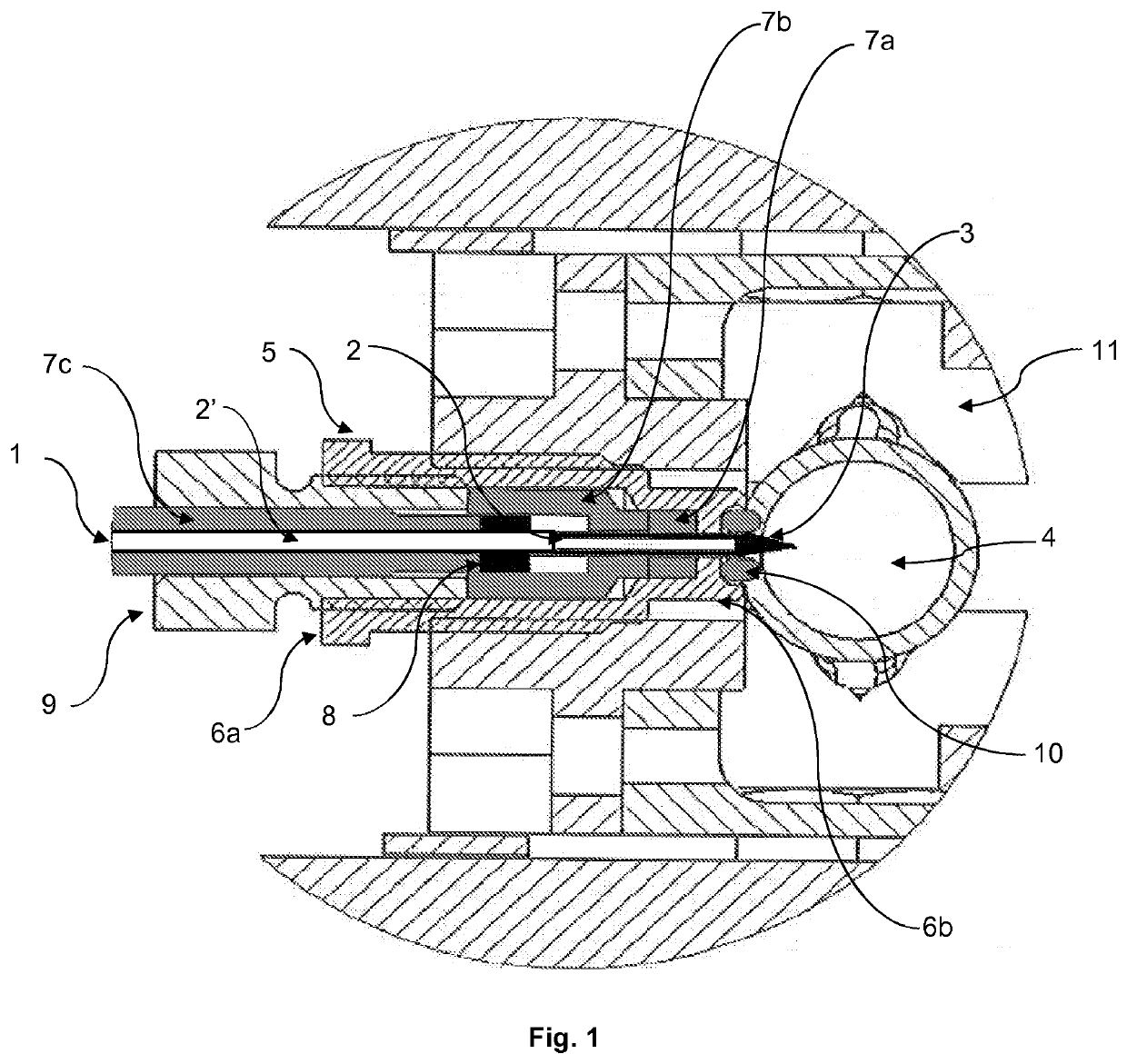
[0064]Making reference to FIG. 1, the device according to the invention comprises a needle 1 fluidically connected to an analysis compartment and more particularly to a cell comprised in the analysis compartment (not illustrated in the figures). During use, the longitudinal axis of the needle 1 of the device according to the invention is preferably oriented horizontally (parallel to the plane of the horizon), as shown in FIG. 1. The needle 1 is configured to pierce an object such as a vessel (as described in detail bellow) in order to transfer a gas contained in the vessel.

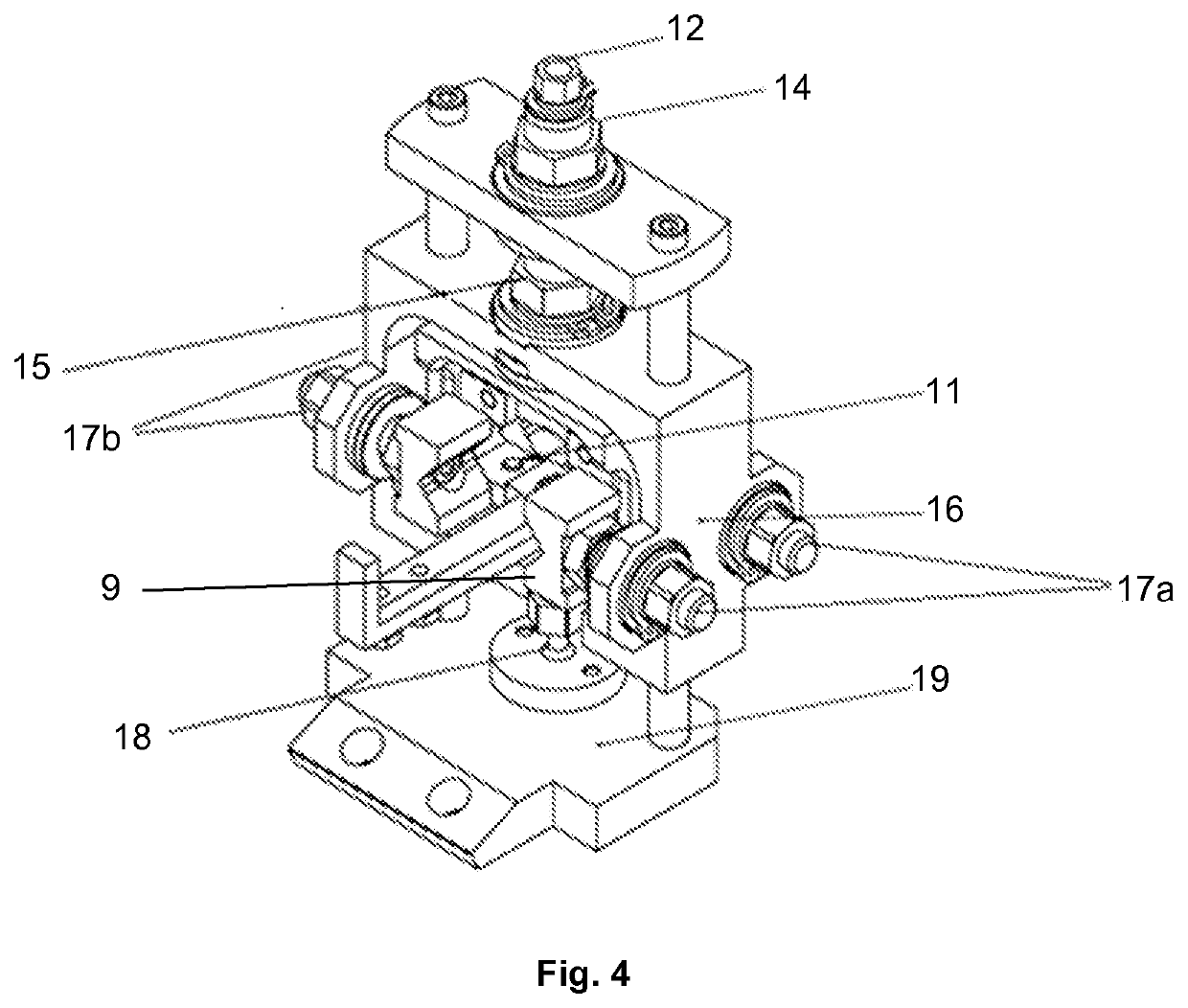
[0065]The needle 1 has a longitudinal axis and comprises a proximal part 2 and a distal part 3. By “proximal” is meant a part of the needle that is connected to th...


PUM

PropertyMeasurementUnit
pressureaaaaaaaaaa
pressureaaaaaaaaaa
lengthaaaaaaaaaa

Abstract

The invention relates to a device for determining a volume of gas in a sample contained in a vessel, the device comprising: a frame configured to attach the vessel; a needle having a longitudinal axis, comprising a proximal part and a distal part, the distal part being configured to pierce the vessel and the proximal part comprising a lumen; and an analysis compartment comprising a cell in fluid communication with the lumen of the proximal part of the needle. The invention also relates to a method for determining a volume of gas in a sample contained in a vessel.

Description

TECHNICAL FIELD[0001]The present invention relates to a device for determining a volume of gas in a sample. The present invention also relates to a method for determining a volume of gas in a sample, the method being implemented in the above-mentioned device.TECHNICAL BACKGROUND[0002]During hydrocarbon exploration and drilling, it is necessary to analyze samples of the rock particles brought up in the drilling mud to determine the proportion of organic matter (oil and gas) in the rock. Until now, this has been done by collecting a sample, placing the sample of the rock particles in a vessel (dish, boat or crucible) within a heated electric pyrolysis furnace, passing a suitable inert carrier gas (helium or nitrogen) over the sample, and analyzing the resultant gaseous samples derived at various temperatures from the pyrolysis of the organic matter in the rock. Thus, upon testing successive samples from different drilling levels, the presence of oil or gas can be detected.[0003]Furthe...

Claims


Application Information

Patent Timeline
Patent Type & Authority Applications(United States)
IPC IPC(8): G01N7/16G01N33/24G01N1/24G01N1/22
CPCG01N7/16G01N33/241G01N1/24G01N1/2226G01N2001/247G01N2001/2229
Inventor COUCHOU-MEILLOT, GILLESPOCHITALOFF-HUVALE, PAUL
Owner TOTALENERGIES SE
Why Eureka
Try Eureka