Power supply system and control device

a power supply system and control device technology, applied in the direction of battery/fuel cell control arrangement, safety/protection circuit, transportation and packaging, etc., can solve the problem of not providing a control device suitable for controlling a battery string

Pending Publication Date: 2022-09-29
TOYOTA JIDOSHA KK
View PDF0 Cites 0 Cited by
  • Summary
  • Abstract
  • Description
  • Claims
  • Application Information

AI Technical Summary

Benefits of technology

[0011]The battery circuit having the above-described configuration enables batteries to be appropriately connected to and disconnected from the power supply circuit by the first switch and the second switch.
[0017]The above-described configuration enables the battery string including many batteries to be controlled appropriately.
[0020]For electrically-driven vehicles that are widespread currently, either nickel-metal hydride battery or lithium-ion battery is often used as a battery storing power for driving the vehicle. The above-described power supply system can appropriately control a heterogeneous battery mixture string manufactured from both the nickel-metal hydride battery and the lithium-ion battery that were used for the electrically-driven vehicles. Thus, the batteries used for the electrically-driven vehicles can be used effectively.
[0028]Depending on the required degree of power adjustment and the required time duration for power adjustment, the control device can selectively cause discharging of the first battery, discharging of the second battery, discharging of both the first battery and the second battery, and repeated charging and discharging of at least one of the first battery and the second battery. The above-described configuration facilitates appropriate power adjustment of the external power supply.

Problems solved by technology

However, Japanese Patent Laying-Open No. 2018-074709 does not provide a control device suitable for controlling a battery string (hereinafter, also referred to as a “heterogeneous battery mixture string”) including dissimilar batteries in a mixed state.

Method used


Image

  • Power supply system and control device
  • Power supply system and control device
  • Power supply system and control device

Examples


Embodiment Construction

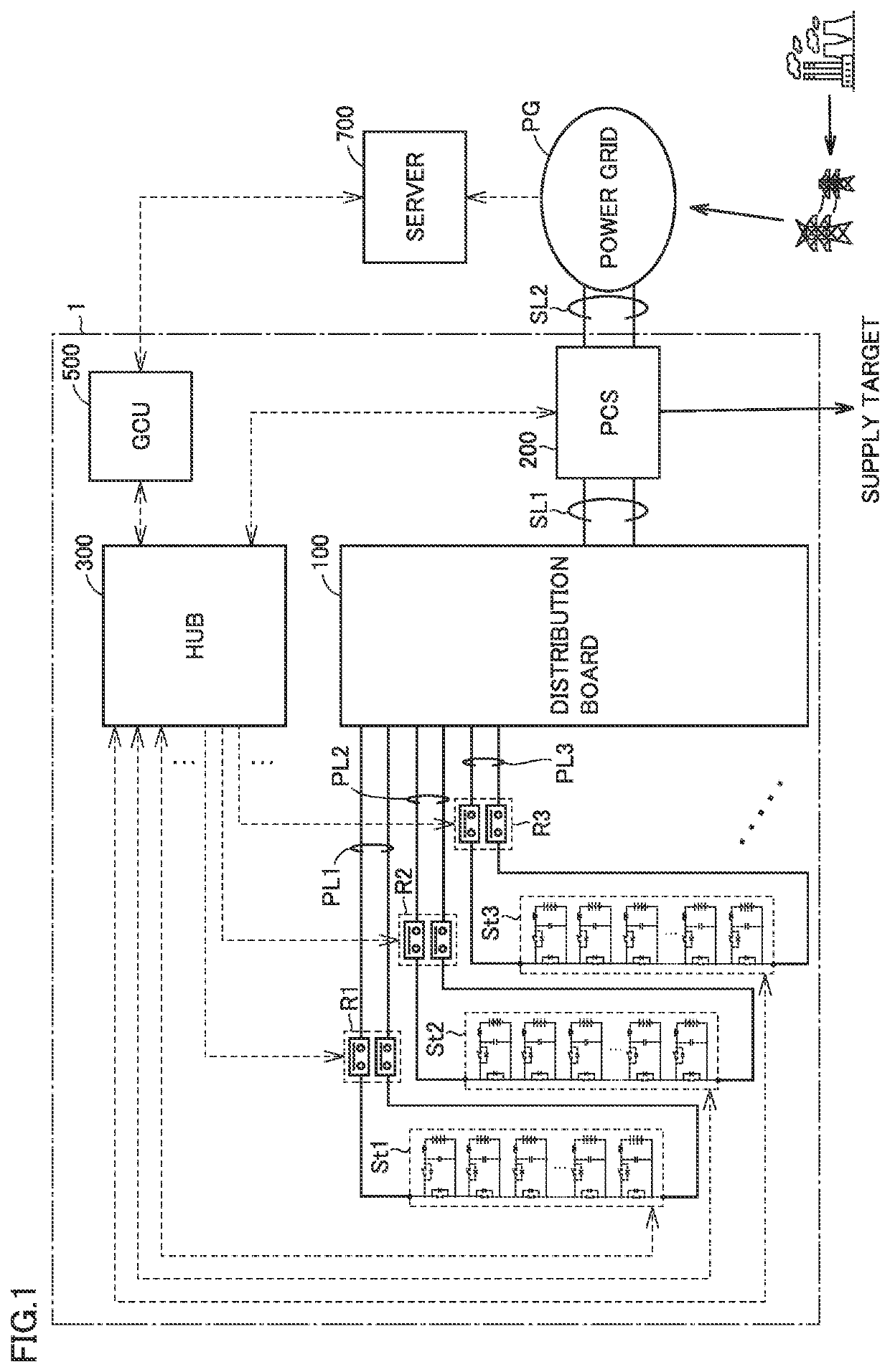
[0052]Embodiments of the present disclosure will be described in detail below with reference to the drawings. The same or corresponding elements in the drawings have the same reference characters allotted and description thereof will not be repeated. FIG. 1 is a diagram showing a configuration of a power supply system according to this embodiment. Referring to FIG. 1, power supply system 1 includes battery strings St1, St2, St3, . . . distribution board 100, PCS (Power Conditioning System) 200, HUB 300, and GCU (Group Control Unit) 500. The battery strings St1, St2, St3, . . . included in the power supply system 1 may have different configurations, but in this embodiment, they have the same configuration. Hereinafter, each of the battery strings St1, St2, St3, . . . will be referred to as a “battery string St” unless they are described in a distinguished manner.

[0053]The battery strings St1, St2, St3, . . . are connected to the distribution board 100 via electric wires PL1, PL2, PL3...


PUM


Abstract

A control device classifies a plurality of batteries included in a battery string into a first battery (e.g., Ni-MH) and a second battery (e.g., LiB). When a predetermined first condition is satisfied, the control device connects, to a power supply circuit, only the first battery among the batteries included in the battery string. When a predetermined second condition is satisfied, the control device connects, to the power supply circuit, only the second battery among the batteries included in the battery string.

Description

CROSS REFERENCE TO RELATED APPLICATIONS[0001]This nonprovisional application is based on Japanese Patent Application No. 2021-053230 filed on Mar. 26, 2021 with the Japan Patent Office, the entire contents of which are hereby incorporated by reference.BACKGROUNDField[0002]The present disclosure relates to a power supply system and a control device, and more particularly, to a technique for controlling a battery string.Description of the Background Art[0003]Japanese Patent Laying-Open No. 2018-074709 discloses a power supply system including a power supply circuit, a battery string connectable to the power supply circuit, and a control device for controlling the battery string. The battery string includes a plurality of battery circuits connected to each other. Each of the plurality of battery circuits includes a battery in a manner connectable to and disconnectable from the power supply circuit. The control device can adjust the output voltage of the battery string to a desired leve...

Claims


Application Information

Patent Timeline
Patent Type & Authority Applications(United States)
IPC IPC(8): H02J7/00
CPCH02J7/0019H02J7/0048H02J7/0031H02J7/0063H02J7/0013H02J7/0025B60L58/18H02J7/00047H02J7/0032H02J3/32H02J7/0016
Inventor MITSUI, MASAHIKO
Owner TOYOTA JIDOSHA KK
Why Eureka
Try Eureka