
Dynamic monitoring system with radio-frequency identification

a dynamic monitoring and radio frequency identification technology, applied in the field of monitoring systems, can solve the problems of increasing the risk of contact, and requiring additional manpower, and achieve the effect of improving the efficiency and accuracy of dynamic monitoring of personnel

Inactive Publication Date: 2022-10-06
SMART AUTOMATION TECH INC
View PDF3 Cites 0 Cited by
  • Summary
  • Abstract
  • Description
  • Claims
  • Application Information

AI Technical Summary

Benefits of technology

The invention is a dynamic monitoring system that uses RFID technology to accurately track and locate people. It detects RFID tags attached to people and uses multiple detectors to increase accuracy. This system helps improve the efficiency of monitoring and tracking individuals.

Problems solved by technology

Dynamic monitoring of personnel has always been an essential issue in today's society.
The existing monitoring system is not only cumbersome and slow, but also requires additional manpower.
When personnel are queuing up to clock in, they also increase the risk of contact, which may cause the spread of diseases.

Method used


Image

  • Dynamic monitoring system with radio-frequency identification
  • Dynamic monitoring system with radio-frequency identification
  • Dynamic monitoring system with radio-frequency identification

Examples


Embodiment Construction

[0022]The aforementioned and other technical content, features and efficacies of the present invention will be clearly presented in the following detailed description of a preferred embodiment with reference to the drawings. The directional terms mentioned in the following embodiment, for example: up, down, above, below, left, right, front or back, etc., are merely directions for referring to the attached drawings. Therefore, the directional terms are used to illustrate but are not intended to limit the present invention.

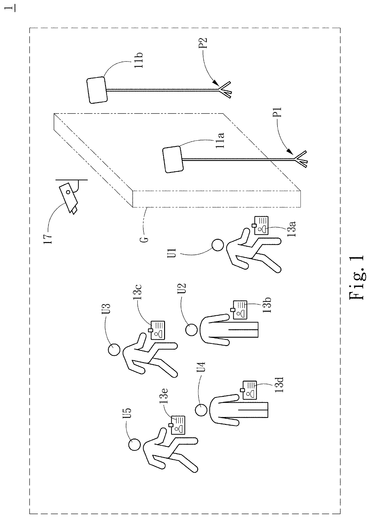
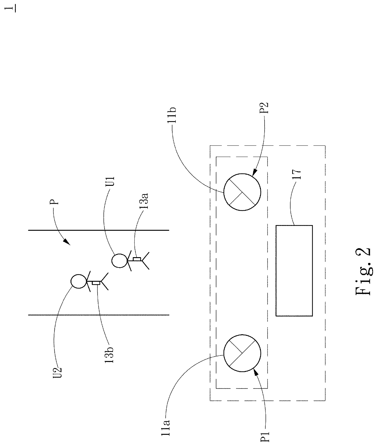
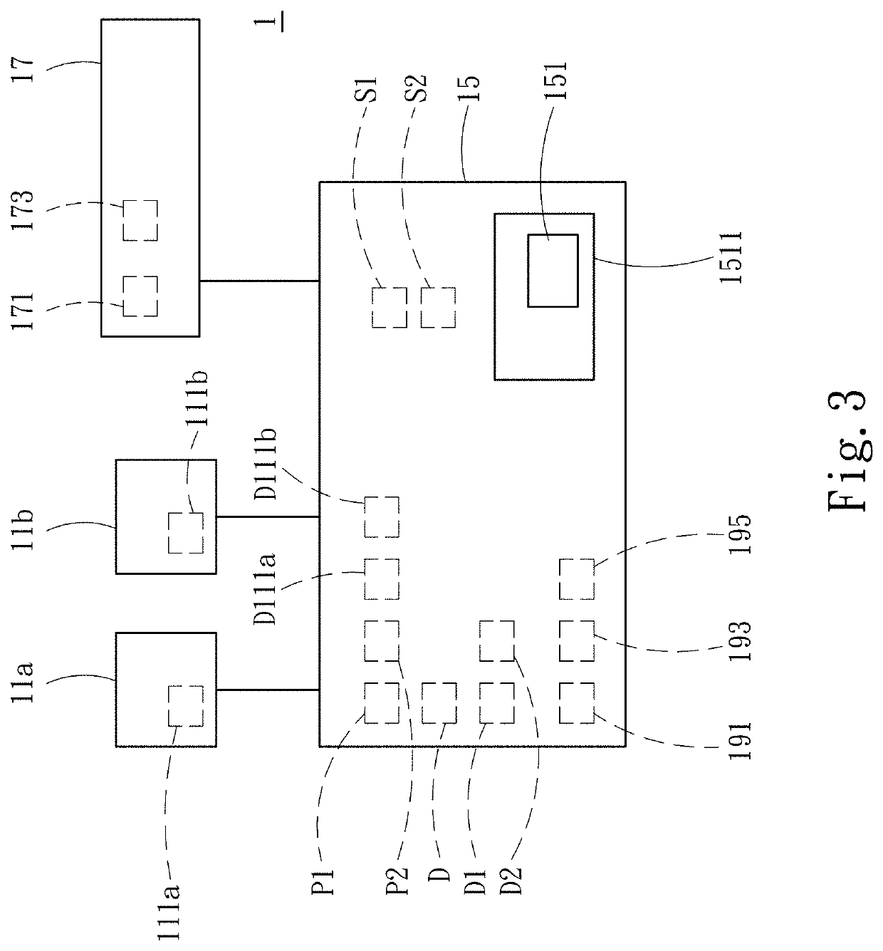
[0023]Please refer to FIG. 1 for a schematic diagram of a dynamic monitoring system with radio-frequency identification according to an embodiment of the present invention. A dynamic monitoring system with radio-frequency identification 1 is capable of accurately and effectively identifying and positioning radio-frequency identification (RFID) tags 13a, 13b, 13c, 13d, 13e, and capable of substantially improving the efficiency and accuracy of dynamic monitoring of pe...


PUM


Abstract

A dynamic monitoring system with radio-frequency identification includes a radio-frequency identification (RFID) tag, at least two radio-frequency identification (RFID) detectors and a processing device. The RFID tag is installed on a moving user. When the user enters a preset detection range, at least two RFID detectors detect the RFID tag and generate an identification signal, respectively. The processing device is coupled to at least two RFID detectors. The processing device generates a distance signal between the RFID tag and the at least two RFID detectors according to the identification signals and positions of the at least two RFID detectors. The processing device generates a positioning signal relevant to a position of the RFID tag within the preset detection range according to the distance signal.

Description

FIELD OF THE INVENTION[0001]The present invention relates to a monitoring system, and particularly to a dynamic monitoring system with radio-frequency identification.BACKGROUND OF THE INVENTION[0002]Dynamic monitoring of personnel has always been an essential issue in today's society. In companies or factories, it is often necessary to control and monitor personnel's entry and exit. In stations, department stores or gatherings, control and monitor of personnel are also crucial tasks.[0003]At present, most monitoring and management systems utilize human power to identify or measure body temperature, and specific personnel are required to identify or measure body temperature of passing personnel, or passing personnel may operate a clock in a device to clock in by themselves. The existing monitoring system is not only cumbersome and slow, but also requires additional manpower. When personnel are queuing up to clock in, they also increase the risk of contact, which may cause the spread ...

Claims


Application Information

Patent Timeline
Patent Type & Authority Applications(United States)
IPC IPC(8): G06K19/077G06K19/07H04N5/33
CPCG06K19/07713G06K19/0717G06K19/07762G06K19/07703G06K19/0723H04N5/33G06K7/10475G06K7/10415G07C9/28H04N23/23
Inventor LIN, TSAI-CHIHLEE, WEN-TZONGLIU, CHE-FUCHEN, RUEI-YANG
Owner SMART AUTOMATION TECH INC
Learn More