High frequency-based array antenna and communication method therefor

a high frequency-based array and antenna technology, applied in the direction of individual energised antenna arrays, radio transmission, transmission, etc., can solve the problems of narrow beamwidth, difficult to achieve high output and high sensitivity at medium or long distances, and limited research on the terahertz band

Active Publication Date: 2022-10-06
ELECTRONICS & TELECOMM RES INST
View PDF16 Cites 0 Cited by
  • Summary
  • Abstract
  • Description
  • Claims
  • Application Information

AI Technical Summary

Benefits of technology

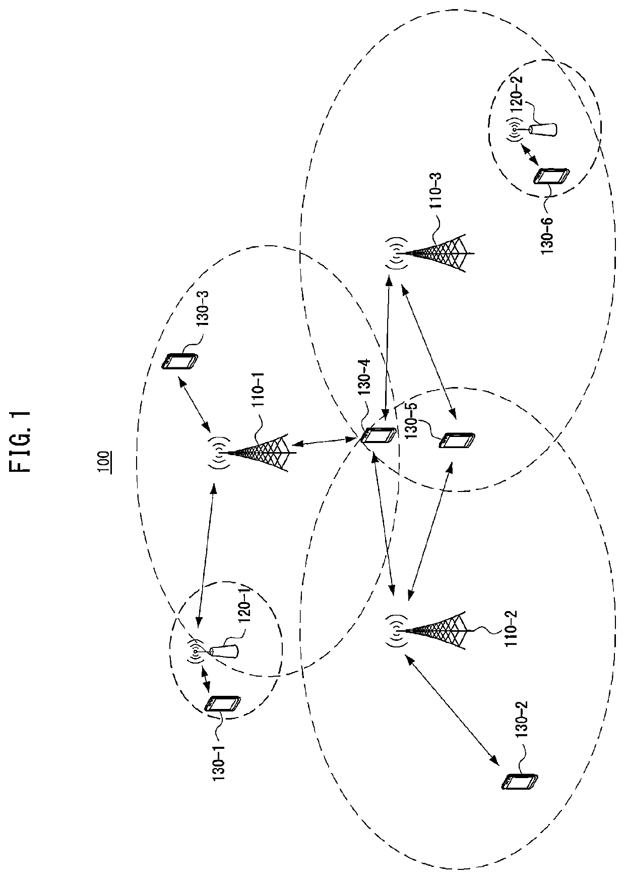
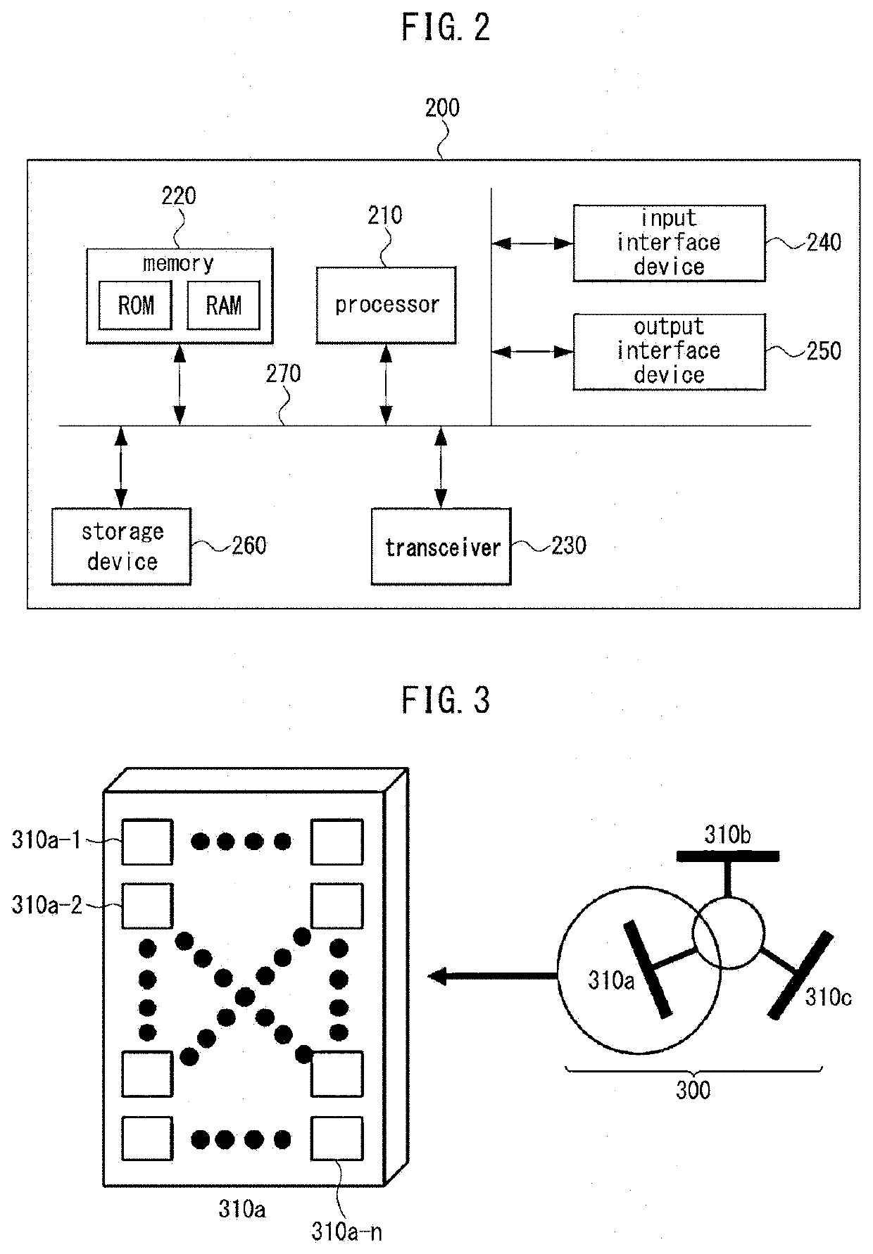
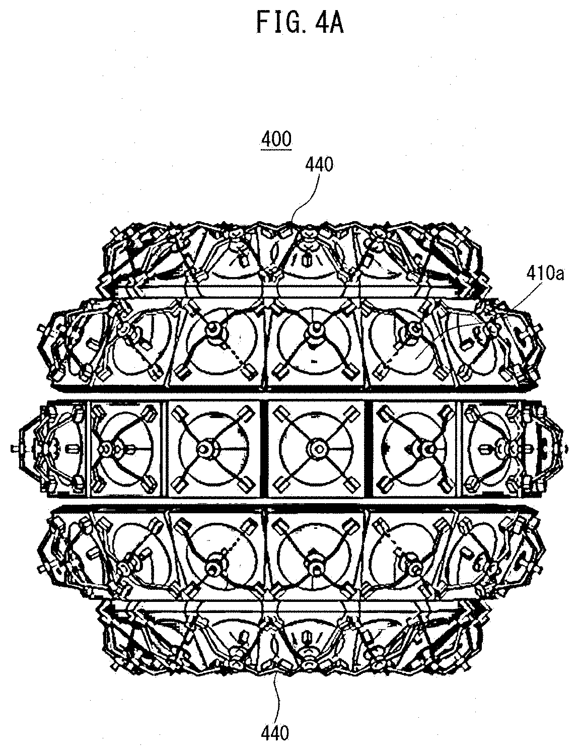
[0020]According to an exemplary embodiment of the present disclosure, a communication node can perform communications by forming beam(s) through the array antenna configured by arranging a plurality of ultra-high frequency high-gain single antennas in a plurality of directions. Here, the array antenna may be configured by arranging the plurality of single antennas in a spherical or cylindrical shape, and each of the single antennas can variably configure a direction of a beam. Accordingly, the array antenna can easily steer beam(s) in all directions around the communication node, a shadow area problem can be solved, and all the surrounding communication areas can be covered even from a low position regardless of the height at which the antenna is mounted. In addition, in the array antenna according to an exemplary embodiment of the present disclosure, a beam coverage can be adjusted according to a density of communication nodes by independently forming or synthesizing beams of the respective single antennas. Accordingly, communication resources can be used efficiently.

Problems solved by technology

Research on the terahertz band has been limited to oscillation and detection devices that generate and detect short-range signals, and it has a disadvantage in that it is not easy to achieve high output and high sensitivity at medium or long distances.
On the other hand, in a study to perform communications in the terahertz band through a beamforming antenna supporting high-gain long-distance transmission, there is a problem in that a shadowing problem due to a narrow beamwidth needs to be solved.

Method used


Image

  • High frequency-based array antenna and communication method therefor
  • High frequency-based array antenna and communication method therefor
  • High frequency-based array antenna and communication method therefor

Examples


Embodiment Construction

[0032]Embodiments of the present disclosure are disclosed herein. However, specific structural and functional details disclosed herein are merely representative for purposes of describing embodiments of the present disclosure. Thus, embodiments of the present disclosure may be embodied in many alternate forms and should not be construed as limited to embodiments of the present disclosure set forth herein.

[0033]Accordingly, while the present disclosure is capable of various modifications and alternative forms, specific embodiments thereof are shown by way of example in the drawings and will herein be described in detail. It should be understood, however, that there is no intent to limit the present disclosure to the particular forms disclosed, but on the contrary, the present disclosure is to cover all modifications, equivalents, and alternatives falling within the spirit and scope of the present disclosure. Like numbers refer to like elements throughout the description of the figure...


PUM


Abstract

An array antenna capable of steering a beam in a first communication node of a wireless communication system may comprise: a plurality of single antennas each capable of variably adjusting a beam steering direction; a plurality of beamforming control units each of which is connected to each of the plurality of single antennas to control a beamforming operation of each of the plurality of single antennas; and an array antenna control unit connected to the plurality of beamforming control units to control a beamforming operation of the entire array antenna, wherein the plurality of single antennas are arranged in a cylindrical shape and are installed to face a direction opposite to a central direction of the cylinder shape, and the array antenna is configured to steer a beam to a predetermined area around the first communication node through at least one single antenna among the plurality of single antennas.

Description

CROSS-REFERENCE TO RELATED APPLICATIONS[0001]This application claims priority to Korean Patent Application No. 10-2021-0043082 filed on Apr. 2, 2021, with the Korean Intellectual Property Office (KIPO), the entire contents of which are hereby incorporated by reference.BACKGROUND1. Technical Field[0002]The present disclosure relates to a high frequency-based array antenna and a communication method using the same, and more particularly, to a high frequency-based array antenna, which can steer a beam around a communication node by configuring the array antenna with a plurality of single antennas, and a communication method using the same.2. Related Art[0003]With the development of information and communication technology, various wireless communication technologies are being developed. Representative wireless communication technologies include long term evolution (LTE) and new radio (NR) defined as the 3rd generation partnership project (3GPP) standards. The LTE may be one of 4th gene...

Claims


Application Information

Patent Timeline
Patent Type & Authority Applications(United States)
IPC IPC(8): H01Q3/36H01Q15/00H01Q5/28H04B7/0426
CPCH01Q3/36H01Q15/0033H01Q5/28H04B7/043H01Q1/246H01Q3/26H01Q19/19H01Q21/205H04B7/0695H01Q21/06H01Q15/14
Inventor LEE, JUNG NAMBYUN, WOO JINKIM, KWANG SEON
Owner ELECTRONICS & TELECOMM RES INST
Why Eureka
Try Eureka