Check patentability & draft patents in minutes with Patsnap Eureka AI!

Terminal structure

a technology of terminals and structures, applied in the direction of multi-conductor cable end pieces, coupling contact members, coupling device connections, etc., can solve the problems of limited shape of the terminal member, limited size reduction of the entire terminal including the waterproofing member, and inability to freely arrange the electric wire, so as to improve the degree of freedom in the arrangement of the electric wire, reduce the size of the waterproofing structure of the terminal, and reduce the number of members

Pending Publication Date: 2022-10-06
HONDA MOTOR CO LTD
View PDF9 Cites 0 Cited by
  • Summary
  • Abstract
  • Description
  • Claims
  • Application Information

AI Technical Summary

Benefits of technology

The present invention aims to solve the problems of large waterproofing structures and limited flexibility in arranging electric wires. It improves the degree of freedom in wire arrangement and reduces the number of related components. In summary, the invention allows for a smaller waterproofing structure and greater flexibility in wire arrangement.

Problems solved by technology

When the terminal member is housed, the size of the waterproofing member needs to be larger than the terminal member and the size reduction of the entire terminal including the waterproofing member is limited to a certain degree.
Accordingly, there are limitations in the shape of the terminal member such as the terminal member being long and the electric wire cannot be freely routed in some cases.

Method used


Image

  • Terminal structure
  • Terminal structure
  • Terminal structure

Examples


Embodiment Construction

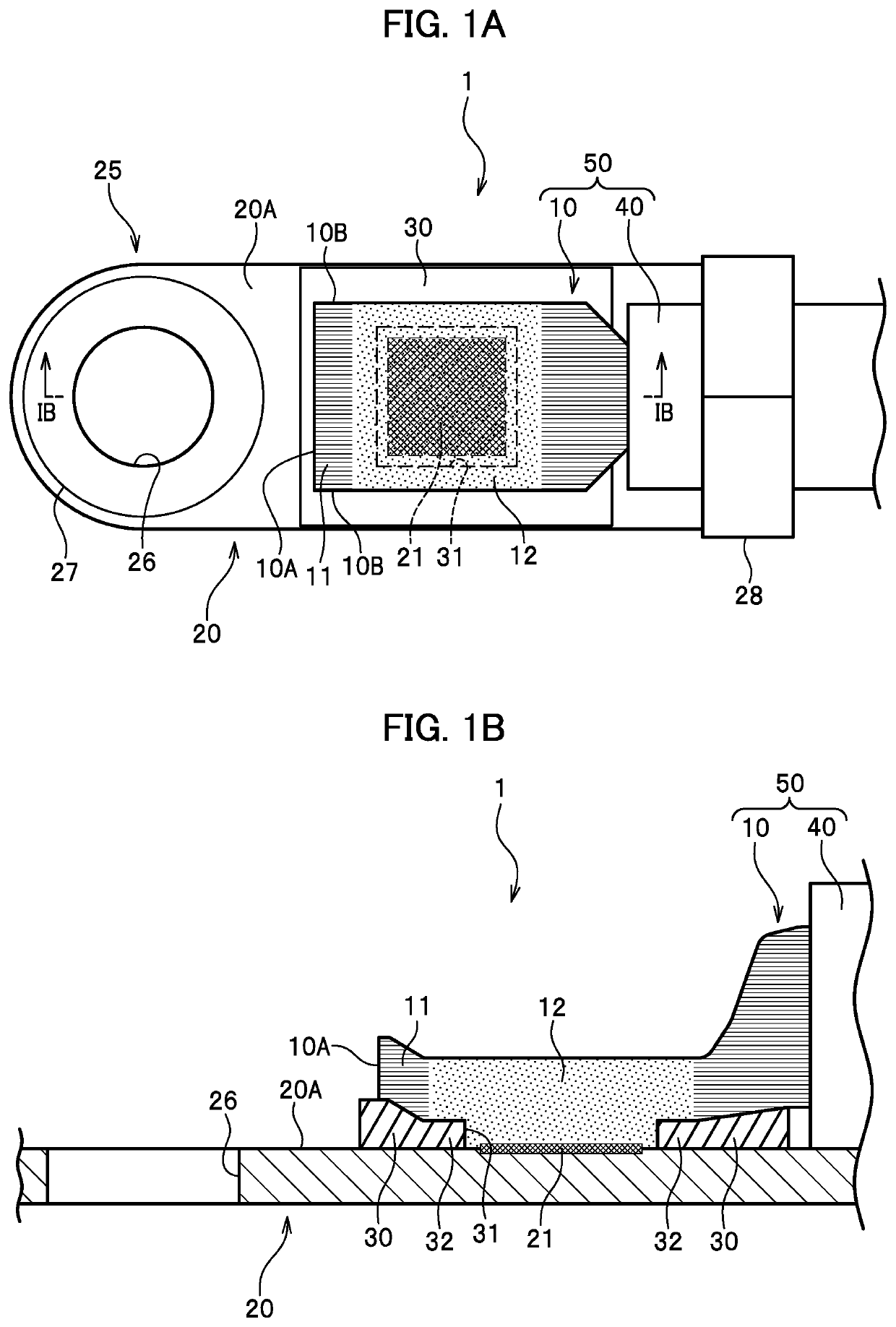
[0015]An embodiment of the present invention is described with reference to the drawings. As illustrated in FIGS. 1A and 1B, a terminal structure 1 according to the embodiment includes a terminal member 20 and an electric wire 50 including a core wire 10.

(Terminal Member)

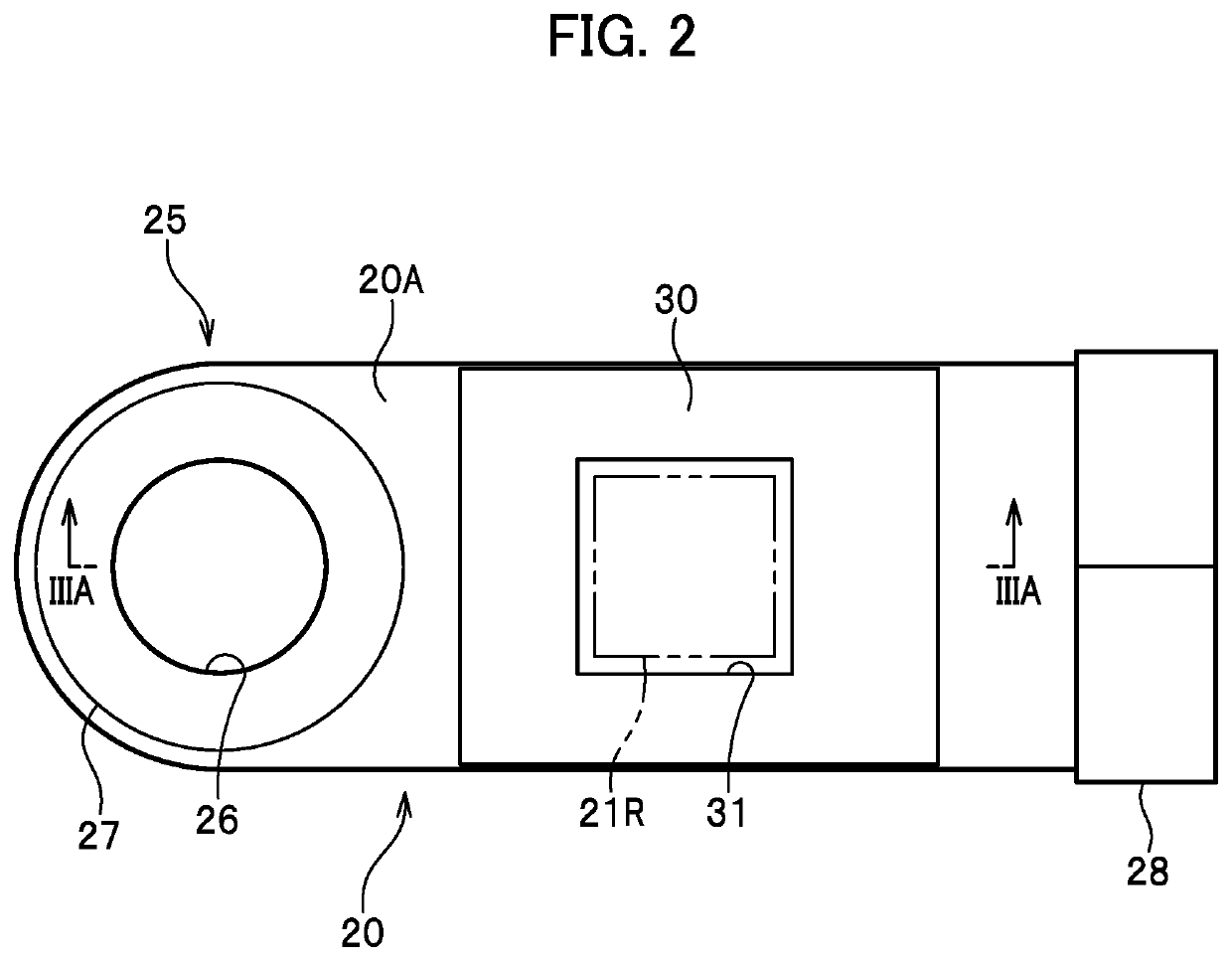
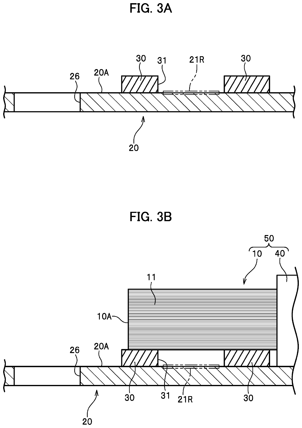
[0016]The terminal member 20 is a member disposed at an end portion of the electric wire 50. The terminal member 20 includes a joining portion 21, a sealing portion 30, and a fitting portion 25. The joining portion 21 and the sealing portion 30 are provided on an arrangement surface 20A on which the core wire 10 of the electric wire 50 is arranged. A material of the terminal member 20 is, for example, a metal.

[0017]The fitting portion 25 is a portion to be fitted to a counterpart terminal to which the electric wire 50 is to be connected, and has a shape matching the counterpart terminal. In this example, a through hole 26 is formed in the fitting portion 25 to facilitate fixation with a screw and an annular electrod...


PUM


Abstract

The terminal structure includes an electric wire including a core wire and a terminal member attached to the electric wire. The terminal member includes a joining portion to which the core wire is joined and the sealing portion surrounding the joining portion and including an opening portion having the joining portion exposed therethrough. The core wire is joined to the joining portion through the opening portion and is in close contact with the sealing portion annularly around the opening portion.

Description

CROSS-REFERENCE TO RELATED APPLICATIONS[0001]The present application claims priority under 35 U.S.C. § 119 to Japanese Patent Application No. 2021-061484, filed Mar. 31, 2021, the contents of which are hereby incorporated by reference in their entirety.BACKGROUND OF THE INVENTION1. Field of the Invention[0002]The present invention relates to a terminal structure of an electric wire.2. Description of the Related Art[0003]A terminal member is attached to a terminal of an electric wire in many cases, the terminal member having a shape matching a counterpart terminal to which the terminal is to be connected. The terminal member has an electric contact point with a core wire of the electric wire. When the terminal member and the core wire are made of different types of metals, attachment of water to the contact point may cause electric corrosion. When the electric corrosion occurs, the resistance of the contact point increases and the attachment strength of the terminal member decreases ...

Claims


Application Information

Patent Timeline
IPC IPC(8): H01R13/52H01R4/10
CPCH01R13/5213H01R4/10H01R13/5221H01R13/02H01R24/00H01R11/11H01R4/183H01R4/70H01R43/0207H01R4/187H01R11/12
Inventor OTA, HIROAKIMUKUMOTO, YASUNORIOHASHI, MASATAKATAGAMI, KOTARO
Owner HONDA MOTOR CO LTD
Features
  • R&D
  • Intellectual Property
  • Life Sciences
  • Materials
  • Tech Scout
  • Unparalleled Data Quality
  • Higher Quality Content
  • 60% Fewer Hallucinations
Learn More