Air conditioner for vehicle

a technology for air conditioners and vehicles, applied in vehicle components, vehicle heating/cooling devices, transportation and packaging, etc., can solve the problems of air passages narrow, air volume reduction, indoor temperature drop, etc., to increase the effective region of air, reduce ventilation resistance, and increase air volume

Pending Publication Date: 2022-10-27
HANON SYST
View PDF0 Cites 1 Cited by
  • Summary
  • Abstract
  • Description
  • Claims
  • Application Information

AI Technical Summary

Benefits of technology

[0038]The air conditioner for a vehicle according to the present invention reduces a space occupied by the support parts of the doors opening and closing the plurality of regions in order to increase an effective region of an air flow of an internal passage, thereby reducing ventilation resistance and increasing an air volume to enhance air conditioning performance and enabling components to be commonly used to prevent an increase of manufacturing costs.

Problems solved by technology

In order to defrost windshields while driving with heat in winter, cold outdoor air with low humidity is effective, but it causes drop of indoor temperature.
The conventional air conditioner for a vehicle has a disadvantage in that the air passage inside the air conditioning case becomes narrow and the air volume is reduced since the plurality of support parts for supporting the plurality of doors must be provided.

Method used


Image

  • Air conditioner for vehicle
  • Air conditioner for vehicle
  • Air conditioner for vehicle

Examples


first embodiment

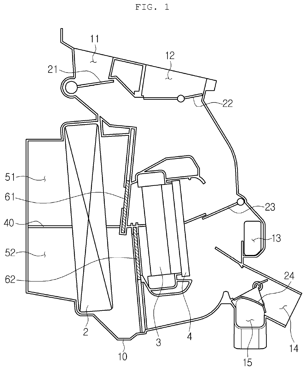
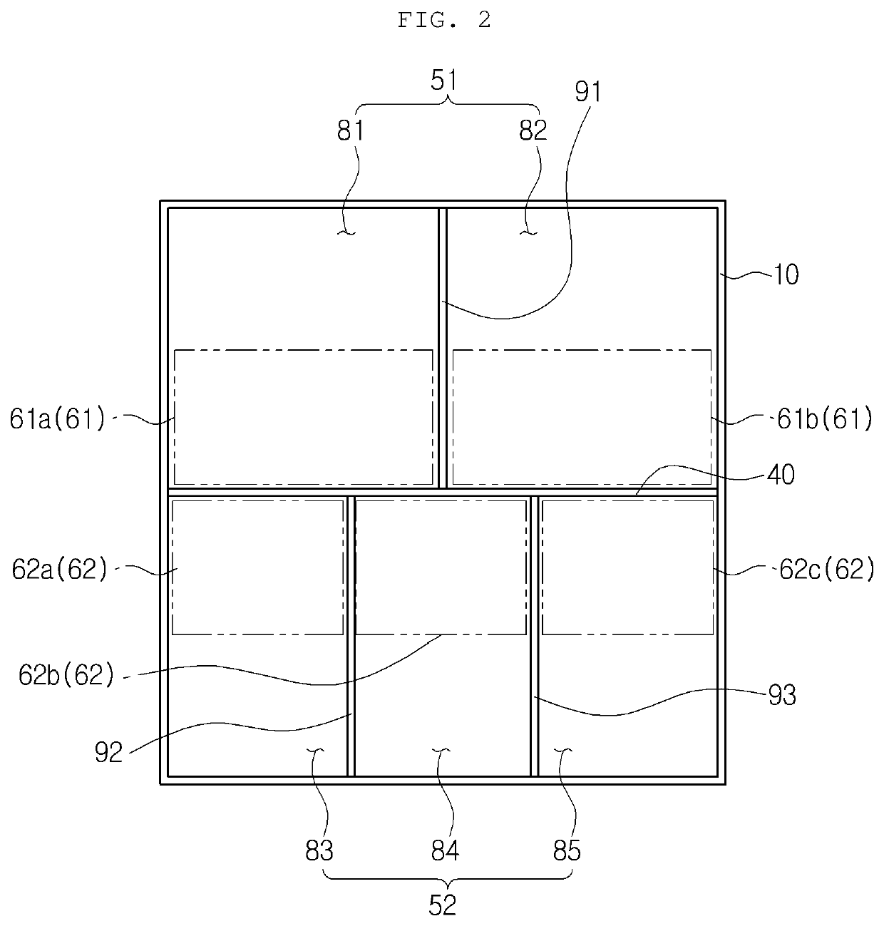
[0087]Referring to FIG. 7 as a first embodiment, the shaft 168 includes a gear part for transmitting driving power to the door. In this instance, the gear part of the shaft driving one door is larger in diameter than the gear part of the shaft driving another door. In detail, the gear part includes: a side gear part 1641 for driving the lower left temperature door 1621 and the lower right temperature door 1623; and a center gear part 1642 for driving the lower center temperature door 1622. The center gear part 1642 is larger in diameter than the side gear part 1641.

[0088]Through such a configuration, the lower center temperature door can be effectively operated when only the diameter of the gear part of the shaft is designed differently without changing the shape of the door.

[0089]FIG. 11 is a perspective view illustrating a lower center temperature door of the air conditioner for a vehicle according to another embodiment of the present invention, FIG. 12 is a plan view of FIG. 11, ...

second embodiment

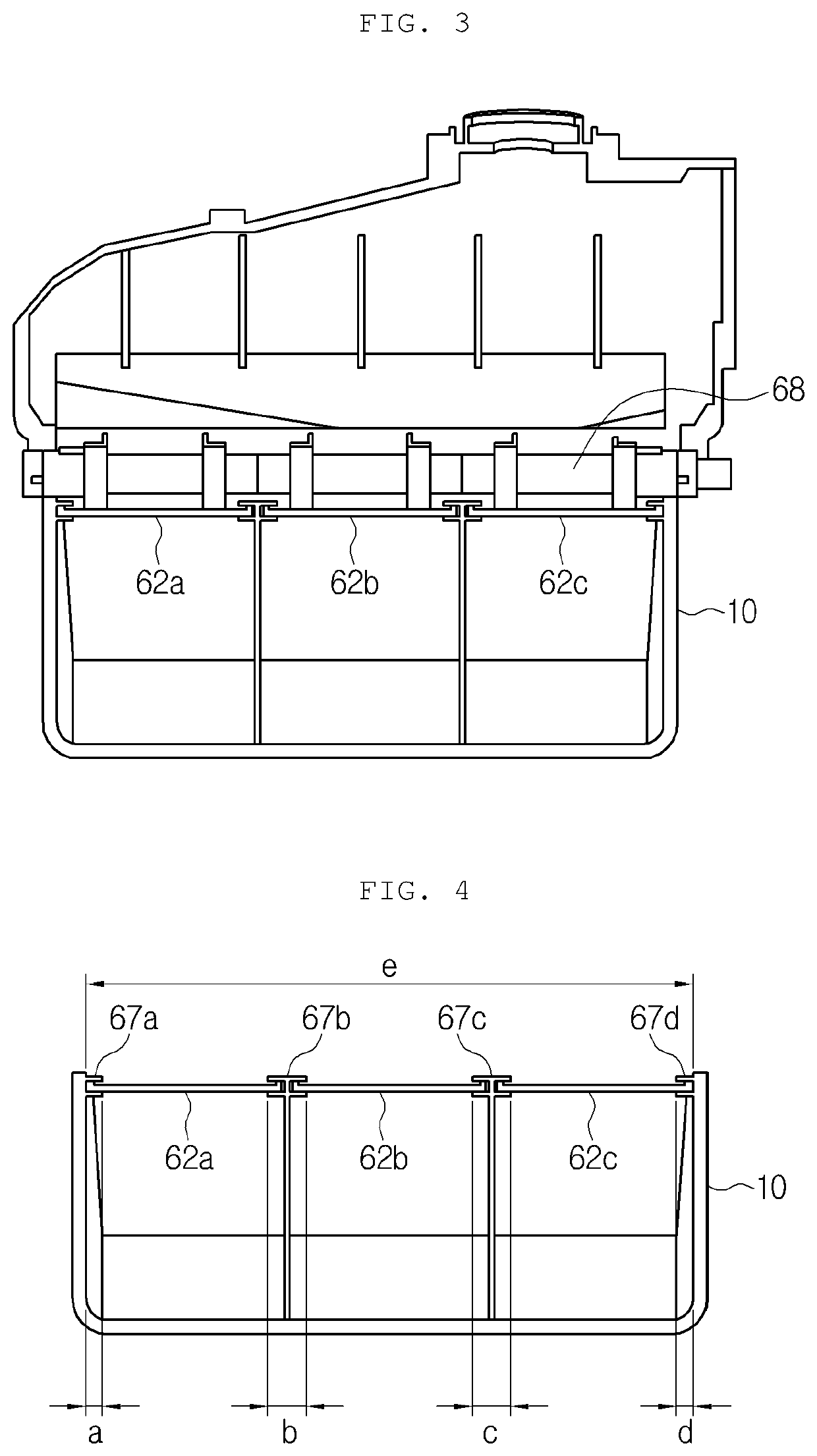
[0090]Referring to FIGS. 11 to 14 as a second embodiment, the gear parts of the shaft 168 are all formed in the same diameter. In this instance, the gear part of one door part engaged with the gear part of the shaft 168 protrudes toward the gear part of the shaft 168 compared to the gear part of the other doors. That is, the gear part of the lower center temperature door 1622 protrudes further toward the shaft 168 than the gear part of the lower left temperature door 1621 and the lower right temperature door 1623.

[0091]In detail, the lower center temperature door 1622 includes a flat plate part 621, a gear part 622, a first stiffness reinforcing part 623, second stiffness reinforcing parts 624 and 625, and a third stiffness reinforcing part 627. The flat plate part 621 is formed in a thin plate shape and forms a main body of the door. The gear part 622 is formed on one surface of the flat plate part 621 and is engaged with the gear part of the shaft 168. The gear part 622 is extende...


PUM


Abstract

Disclosed is a vehicle air conditioner capable of increasing the aft flow effective region of an inner flow path by reducing the space occupied by support parts of doors for opening/closing a plurality of regions. The vehicle air conditioner comprises: an air-conditioning case in which an air flow path is formed; and a cooling heat exchanger and a heating heat exchanger provided in the air flow path of the air-conditioning case, wherein the air flow path is partitioned and divided into a plurality of regions, and has a plurality of doors for opening/closing each region and a shaft for driving the doors, and the distance between one door and the shaft is different from the distance between another door and the shaft.

Description

TECHNICAL FIELD[0001]The present invention relates to an air conditioner for a vehicle and, more specifically, to an air conditioner for a vehicle, which has doors for dividing an air passage into a plurality of regions and opening and closing the corresponding region, and a support structure thereof.BACKGROUND ART[0002]In general, an air conditioner for a vehicle is an apparatus for cooling or heating the interior of the vehicle by cooling or heating through the process of introducing outdoor air into the interior of the vehicle or circulating indoor air of the vehicle. Such an air conditioner for a vehicle includes an evaporator for a cooling action and a heater core for a heating action inside an air-conditioning case, and selectively blows the air cooled by the evaporator or heated by the heater core toward parts of the interior of the vehicle.[0003]Especially, in order to secure defogging performance and maintain a high-performance heating during heating, a two-layer air condit...

Claims


Application Information

Patent Timeline
Patent Type & Authority Applications(United States)
IPC IPC(8): B60H1/00
CPCB60H1/00692B60H1/00842B60H1/00064B60H2001/002B60H2001/00721B60H2001/00135B60H2001/007B60H1/00835
Inventor MAENG, CHAN JOOKIM, YOUNG KEUNJEON, KI MANJUNG, HYUN KWONHAN, GYU IK
Owner HANON SYST
Why Eureka
Try Eureka