Lens device and lens set moving mechanism thereof

a technology of lens set and moving mechanism, which is applied in the direction of instruments, printers, cameras, etc., can solve the problems of resolution dropping sharply, increasing the length of the entire lens, and the way of changing the distance between the lens set (lens group) by the traditional zooming lens is limited to the structure, so as to reduce the lens size

Pending Publication Date: 2022-10-27
VASSTEK INT
View PDF0 Cites 0 Cited by
  • Summary
  • Abstract
  • Description
  • Claims
  • Application Information

AI Technical Summary

Benefits of technology

[0006]In order to achieve the purposes of reducing the size of the miniature lens, not affecting the performance of the lens zooming and focusing, and maintaining the accuracy of the optical axis, through the moving space in the lens device, the lens device and the lens set moving mechanism of the present invention can allow the supporting structure for supporting one lens set to pass the peripheral of another lens set when it moves without the interference. In this way, the distance between the lens sets can be very close, or even zero, without sacrificing the stability when the lens sets are moving.

Problems solved by technology

However, this method causes the resolution to drop sharply.
Nevertheless, the way of changing the distance between the lens sets (lens groups) by the traditional zooming lens is limited to the structure.
This not only increases the length of the entire lens, but also increases the diameter of the lens, which indirectly affects the mobile phone so that the size of the mobile phone is difficult to shrink.

Method used


Image

  • Lens device and lens set moving mechanism thereof
  • Lens device and lens set moving mechanism thereof
  • Lens device and lens set moving mechanism thereof

Examples


first embodiment

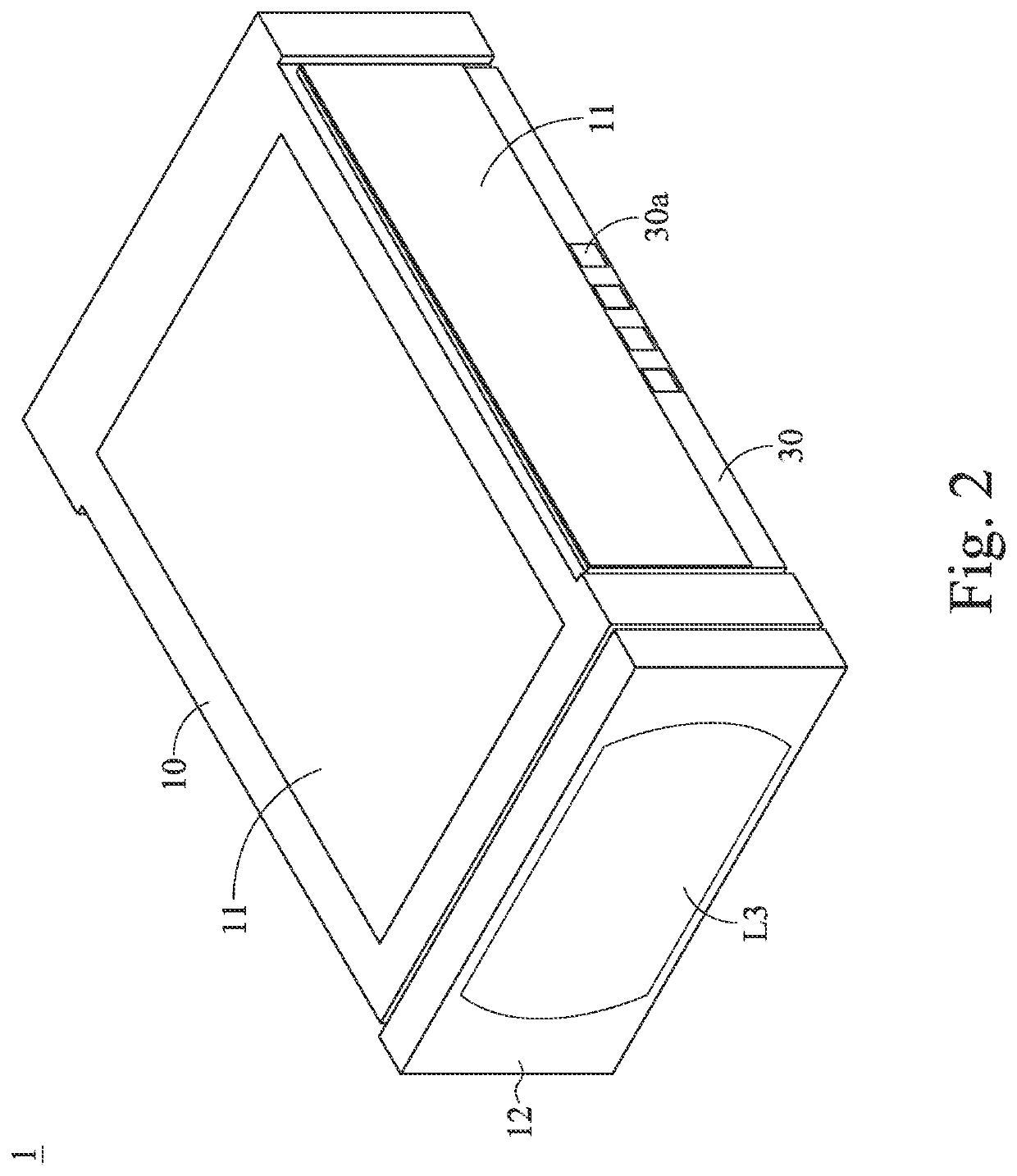
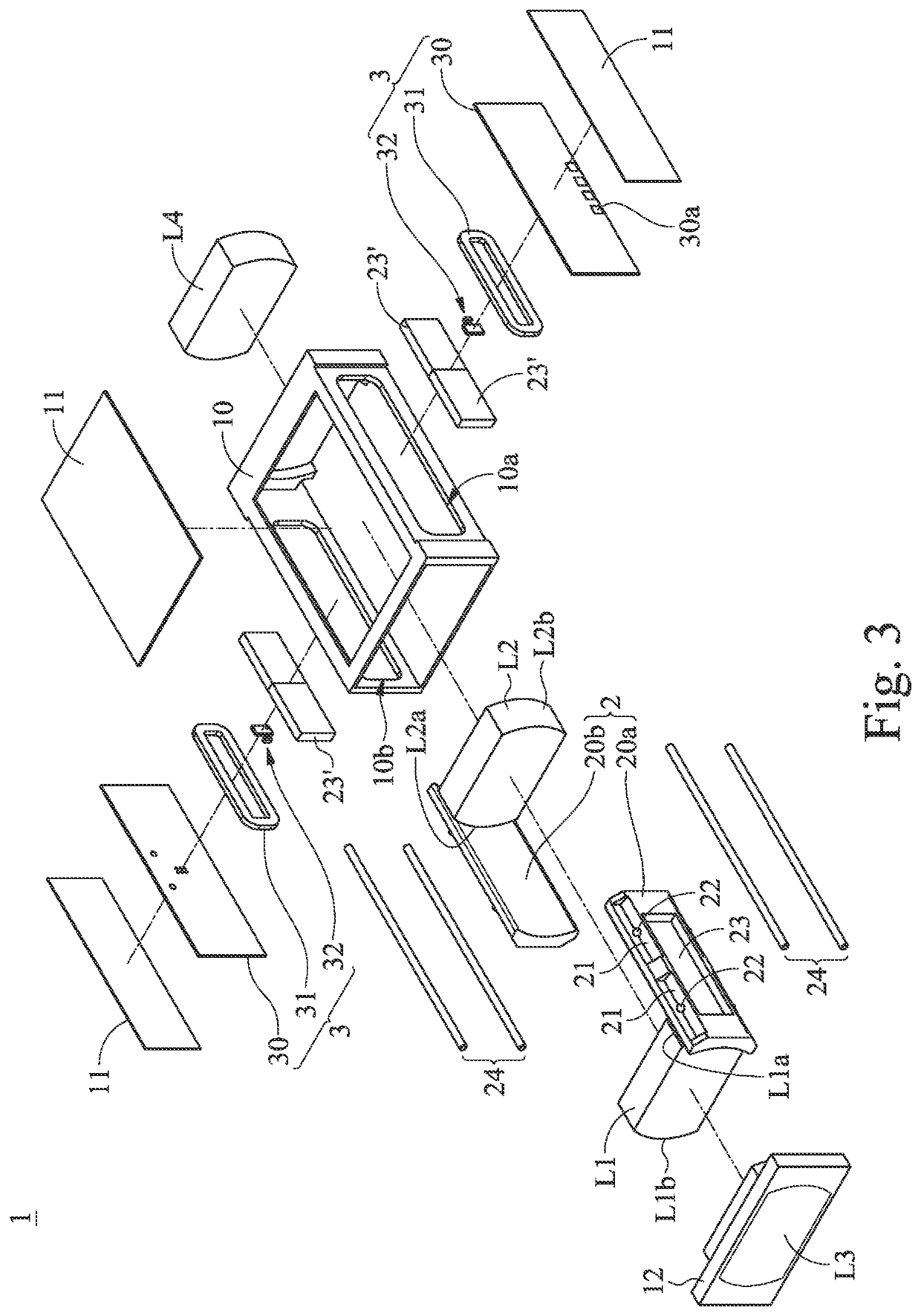
[0023]Please refer to FIGS. 2, 3 and 4, wherein FIG. 2 is a three-dimensional view of the appearance of a lens device 1 according to the present invention, FIG. 3 is an exploded view of the lens device 1 in FIG. 2, and FIG. 4 is a front view of the lens device 1 in FIG. 2, wherein the front cover12 has been removed. As shown in FIGS. 2, 3 and 4, the lens device 1 of the present invention is disclosed. The lens device 1 includes a housing 10. The upper side and the lateral side of the housing 10 have covers 11 to protect the inside. Generally, after the assembly is completed, the covers 11 are disposed as the final packaging. The contacts 30a of the circuit board 30 are exposed under the cover 11 at the lateral side to be electrically connected to the external circuit. The guiding rods 24 are disposed in the corners of the housing 10 in the direction parallel to the direction of optical axis of each lens set (the first lens set L1 to the fourth lens set L4), wherein two guiding rods ...

second embodiment

[0027]Please refer to FIG. 8, which is a cross-sectional view of a lens device 1′ according to the present invention, showing how to focus. FIG. 8 discloses that the lens device 1′ has a fifth lens set L5 fixed on the second side 10b in the housing 10, and the first lens set L1 is borne by the movable stage 20a so that it can move forward and backward to achieve the effect of focusing. The first end L5a of the fifth lens set L5 is used to be fixed on the second side 10b, and the thickness D1 of the space between the second end L5b and the first side 10a is larger than the thickness 20T of the first stage 20a so that a gap 20c is formed. In other words, a moving space is formed between the second end L5b and the first side 10a for the movable stage 20a to pass therethrough.

third embodiment

[0028]Please refer to FIG. 9, which is a three-dimensional view of a lens device according to the present invention. The included angle between the first stage 20a and the second stage 20b in FIG. 9 relative to the optical axis A is about 90 degrees. However, the included angle between the first stage 20a and the second stage 20b in the previous embodiments is 180 degrees; the reason why it is 180 degrees is that the present invention mostly uses the voice coil motor to drive each stage 20a, 20b so that there will be the problem of the magnetic field interference if the first stage 20a and the second stage 20b are too close. Nevertheless, if other driving methods which do not generate the magnetic field interference are used, the choice of the relative positions between the stages 20a, 20b is wider. As shown in FIG. 9, the two stages 20a, 20b are disposed adjacent to each other. The first stage 20a is slidable on the first track 24a, the second stage 20a is slidable on the second tr...


PUM


Abstract

A lens device is disclosed. The lens device includes a housing; a first lens set having a first end and a second end, wherein the first end is fixed on one of the housing and a first stage, and a moving space is formed between the second end and the housing; a second stage disposed on the housing, and slidable in the moving space; and a second lens set disposed on the second stage, and configured to perform a focusing function of the lens device.

Description

CROSS-REFERENCE TO RELATED APPLICATION AND CLAIM OF PRIORITY[0001]The application claims the benefit of Taiwan Patent Application No. 110114994, filed on Apr. 26, 2021, at the Taiwan Intellectual Property Office, the disclosures of which are incorporated herein in their entirety by reference.FIELD OF THE INVENTION[0002]The present invention relates to a lens and the lens set moving mechanism thereof, and more particularly to a miniature lens and the lens set moving mechanism thereof used in a handheld electronic device such as a mobile phone.BACKGROUND OF THE INVENTION[0003]Hand-held electronic devices such as mobile phones are now the most commonly used photographic devices. Due to the small size of the hand-held electronic device, the lens zooming method used to be digitally zoomed; that is, only a small area is captured on the photosensitive element to achieve the enlargement of the target. However, this method causes the resolution to drop sharply. Afterwards, the traditional zo...

Claims


Application Information

Patent Timeline
Patent Type & Authority Applications(United States)
IPC IPC(8): G02B7/09G02B7/08G02B13/00H04N5/225
CPCG02B7/09G02B7/08G02B13/009H04N5/2253G02B7/04G02B7/10G03B13/34G03B30/00H04N23/57H04N23/55G02B7/102H02K41/0356G03B5/00G03B3/10H04N23/54
Inventor HUANG, CHIH-MING
Owner VASSTEK INT
Why Eureka
Try Eureka