Tool for rotatable joints

Pending Publication Date: 2022-11-03
SANDVIK SRP
View PDF0 Cites 0 Cited by
  • Summary
  • Abstract
  • Description
  • Claims
  • Application Information

AI Technical Summary

Benefits of technology

The present invention describes a tool for safely and efficiently opening and closing large rotatable joints. The tool includes two grippers that are moved by actuators and a lever arrangement that fits over the surface of the main shaft. The grippers have a cylindrical surface that matches the shape of the main shaft. This tool helps to improve the friction characteristics of the grippers and ensures safe and efficient installation work.

Problems solved by technology

The rotatable joint has the tendency of tightening up as the crusher is running, so a lot of separating force is needed to open the joint.
Using these tools is also demanding from the viewpoint of work safety, and is a factor in causing accidents at work.

Method used


Image

  • Tool for rotatable joints
  • Tool for rotatable joints
  • Tool for rotatable joints

Examples


Embodiment Construction

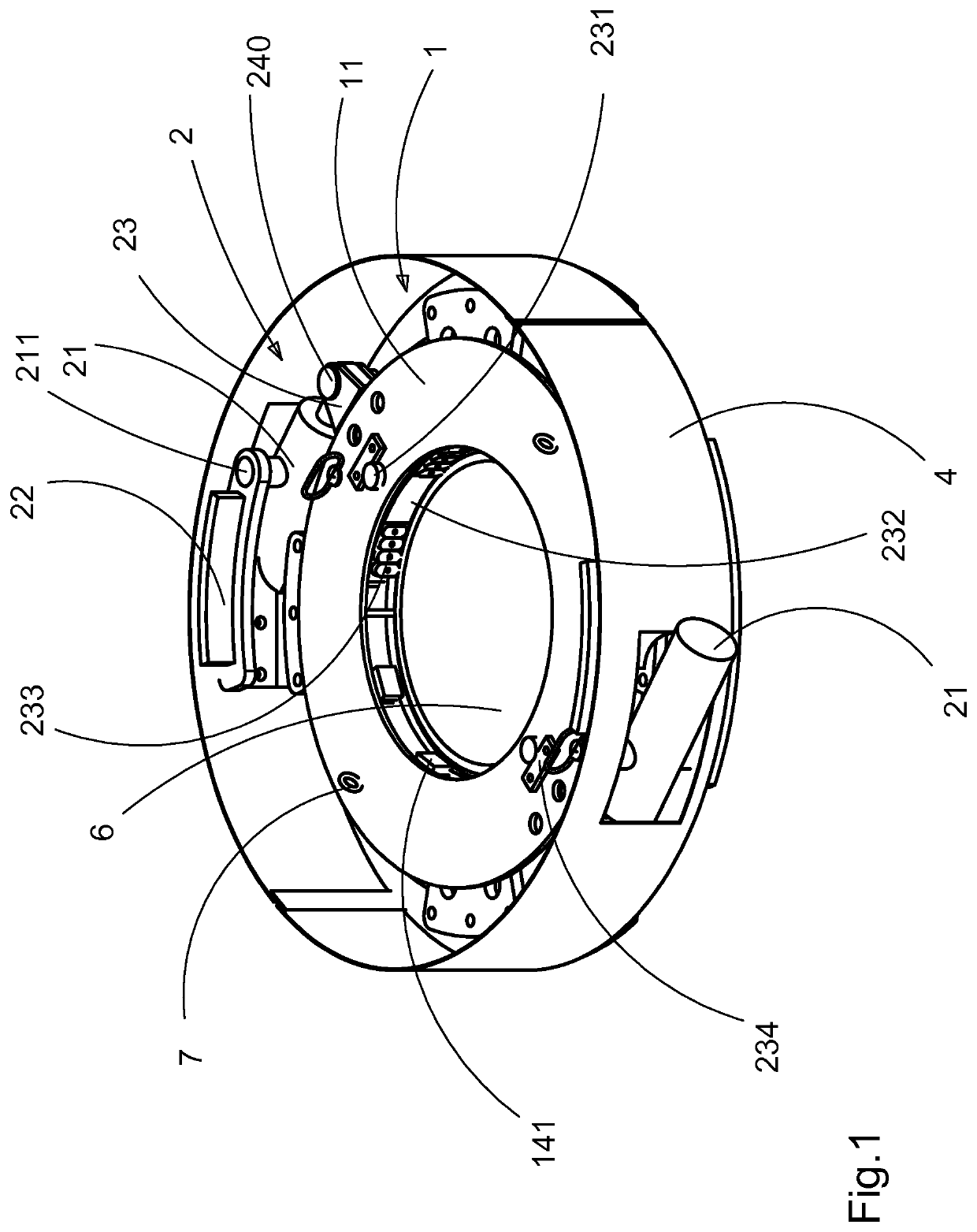
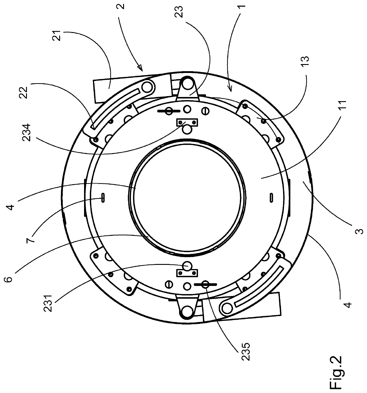
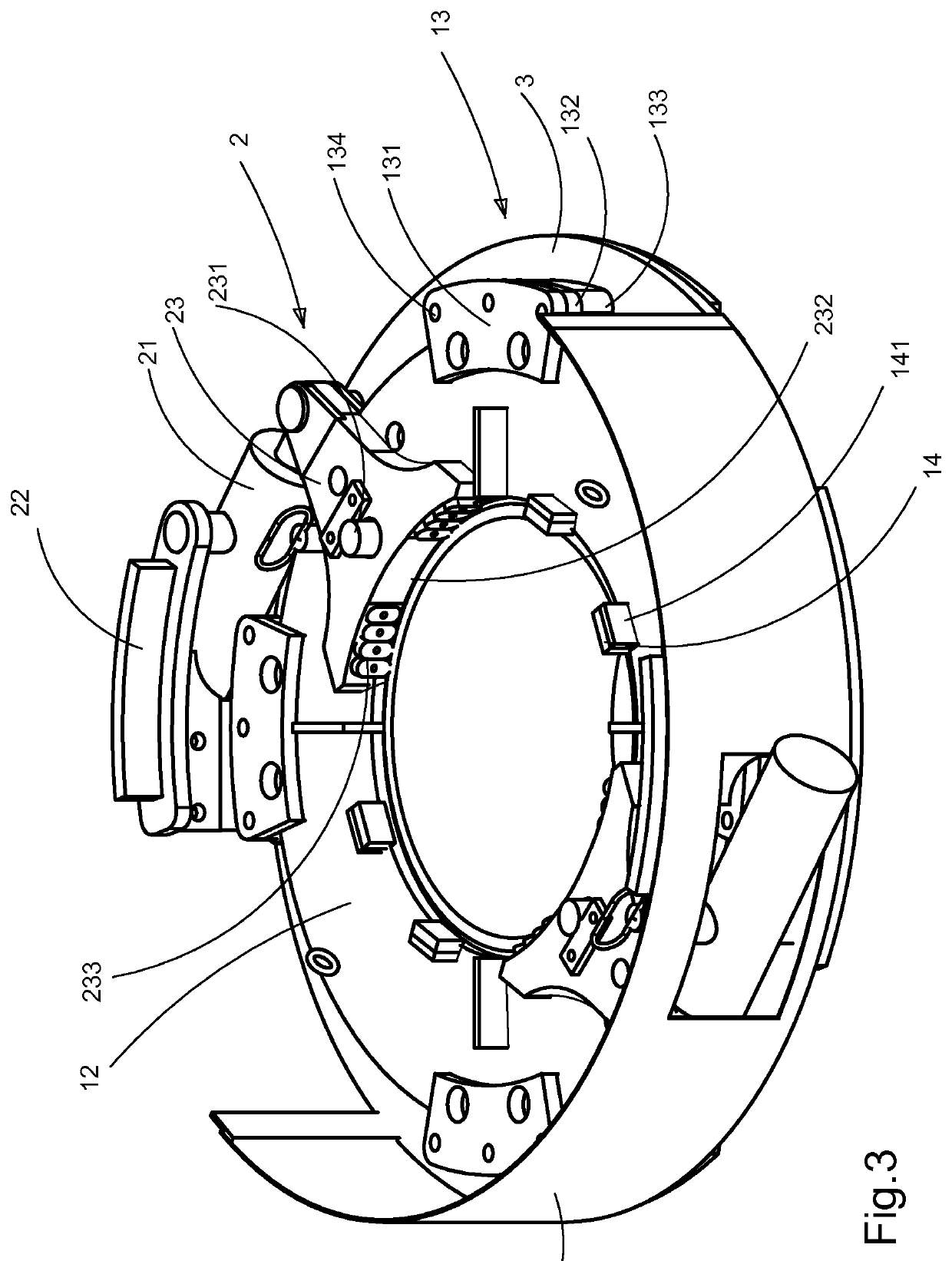
[0019]FIGS. 1 to 8 show a tool that includes a slewing ring 1, a first grip member 3, a second grip member 2, and protective plates 4.

[0020]The slewing ring 1 consists of an annular upper plate 11 and, placed lower, an annular guide plate 12, between which plates are adapted grippers 23 of the second grip member 2. The centre hole of the plates is slightly larger than a shaft 6 of a rotatable joint. The plates 11 and 12 are interconnected by radial plate pieces 15 the height of which is slightly larger than the thickness of the gripper 23. On the edge of the centre hole of the guide plate 12, guide pieces 14 are arranged, which centre the tool onto the shaft. There are protective pieces 141 in connection with the guide pieces to prevent damages onto the surface of the shaft 6. On the upper plate 11, lifting lugs 7 are arranged.

[0021]The guide plate 12 is adapted to slide in slots 135 of slide pieces 13 which are in connection with the first grip member 3. The slide pieces consist of...


PUM


Abstract

A tool for opening and / or closing rotatable joints, includes a slewing ring, a first grip member, and a second grip member. The first grip member is an annular plate. The second grip member includes two identical gripper arrangements, which include a gripper, an actuator, and bearing members of the actuator. The slewing ring includes an annular upper plate and an annular guide plate, between which plates grippers of the second grip member are arranged. The guide plate is arranged to slide in slots of slide pieces, which are in connection with the first grip member. The bearing members of the actuators are in connection with the first grip member, which actuators are arranged to move the grippers of the second grip member. The grippers are fastened to the slewing ring in a pivoted manner and arranged to grip the shaft of the joint.

Description

BACKGROUND OF THE INVENTION[0001]The invention relates to a tool for opening and / or closing a rotatable joint. The invention in particular relates to a tool used to open and close a rotatable largish joint.BRIEF DESCRIPTION OF THE INVENTION[0002]Rotatable largish joints are used in connection with crushers and other pieces of heavy machines. For example, an inner mantel of a cone crusher is often fixed to a support cone by a rotatable joint between the thread of the main shaft and a mounting nut. The rotatable joint has the tendency of tightening up as the crusher is running, so a lot of separating force is needed to open the joint. The nut is substantially annular, in other words the wall thickness is much smaller than the nut diameter whereby the nut, when being loosened, tends to bite into the thread due to deformation taking place in the nut. In such a case, it would be advantageous to unfasten of the nut with a force that is evenly distributed on the periphery of the nut. The j...

Claims


Application Information

Patent Timeline
IPC IPC(8): B23P19/06
CPCB23P19/06E21B19/163B25B13/5016B25B5/147B25B21/002B25B28/00
Inventor KARNA, TAISTO
Owner SANDVIK SRP
Why Eureka
Try Eureka