
Electrically motorized pump having a submersible sleeve bearing

Inactive Publication Date: 2006-03-07
MINEBEA CO LTD
View PDF55 Cites 8 Cited by
  • Summary
  • Abstract
  • Description
  • Claims
  • Application Information

AI Technical Summary

Benefits of technology

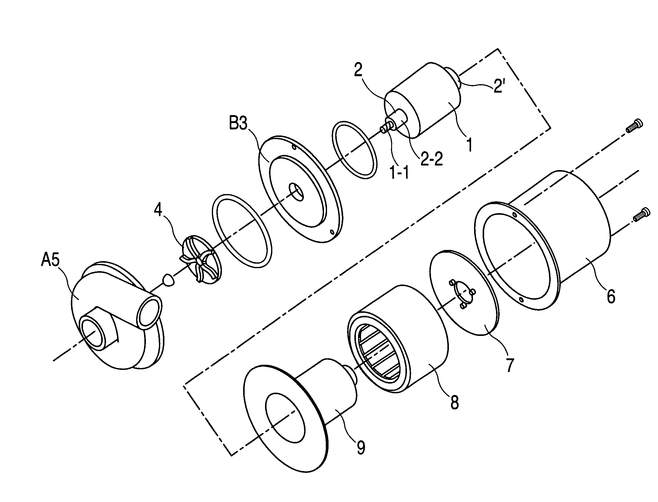
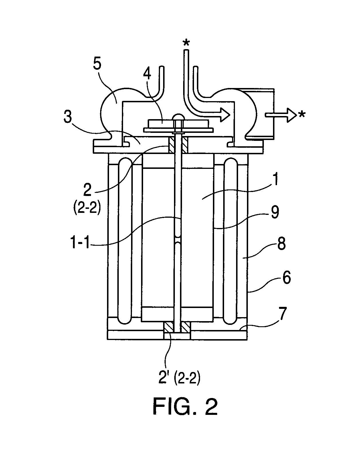
[0024]The present invention overcomes the deficiency of the prior art and provides an electric submersible pump in which a stator is accommodated in the outer peripheral space of a flanged housing and a flanged can seal. A rotor, a rotary shaft, and a sleeve bearing are accommodated in the inner space of the can seal. The sleeve bearing is mounted in a central hole of a substrate of the pump casing. The substrate is secured with the flanges of the housing and can seal, and an impeller is mounted on the distal end portion of the rotary shaft that is mounted inside the pump casing. The sleeve bearing is composed basically of a shaft and a sleeve and the sleeve or shaft is manufactured from a synthetic resin composition in which a fine powder of RBC or CRBC is dispersed homogeneously. The submersible sleeve bearing has improved mechanical properties, improved friction characteristics, productivity, and cost.
[0025]The synthetic resin composition obtained by mixing a synthetic resin with an RBC or CRBC reduced to a fine powder with a mean particle size of 300 μm or less, preferably 10–100 μm, even more preferably 10–50 μm, demonstrates exceptional sliding property in water.
[0026]More specifically, the resin composition in which a fine powder of RBC or CRBC is uniformly dispersed, in particular at a weight ratio of the fine powder of RBC or CRBC to a synthetic resin of 10–70:90–30, yields a molding resin, such that the sleeve bearing made from the molding resin demonstrates excellent wear characteristics in liquids such as water, alcohols, ethylene glycol, and mixtures thereof.

Problems solved by technology

The number of revolutions of such pump could not be controlled in a fine manner.
Furthermore, when the engine stops, the pump stops immediately thereby causing troubles.
When the rotor is used at high revolutions for a long period of time, the O-ring deteriorates causing a loss in energy, also the sealing material, which is in close contact with the shaft causes a loss in energy.

Method used


Image

  • Electrically motorized pump having a submersible sleeve bearing
  • Electrically motorized pump having a submersible sleeve bearing
  • Electrically motorized pump having a submersible sleeve bearing

Examples


working example 1

Preparation of Fine Powder of RBC

[0045]A total of 750 g of defatted bran obtained from rice bran and 250 g of a liquid phenolic resin (resol) were mixed and blended while being maintained at a temperature of 50–60° C. As a result, a homogeneous mixture having plasticity was obtained.

[0046]The mixture was baked for 100 minutes at a temperature of 900° C. in nitrogen atmosphere in a rotary kiln to obtain carbonized fired material. The carbonized fired material was ground with a grinding machine and passed through a 150-mesh sieve to obtain a fine powder of RBC with a mean particle size of 140–160 μm.

Preparation of a Composition Containing Fine Powder of RBC and Synthetic Resin

[0047]A total of 500 g of the above obtained fine powder of RBC and 500 g of Nylon 66 powder were mixed and blended while being maintained at a temperature of 240–290° C. As a result, a homogeneous mixture having plasticity was obtained. The content ratio of the fine powder of RBC was 50 wt. %.

Fabrication of Slee...

working example 2

[0049]A fine powder of RBC with a mean particle size of 140–160 μm was obtained by using the method described in Working Example 1.

Preparation of a Composition Containing Fine Powder of RBC and Synthetic Resin

[0050]A total of 700 g of the above fine powder of RBC and 300 g of Nylon 66 powder were mixed and blended while being maintained at a temperature of 240–290° C. As a result, a homogeneous mixture having plasticity was obtained. The content ratio of the fine powder of RBC was 70 wt. %.

Fabrication of Sleeve Bearing and Application to Submersible Pump

[0051]The resin composition obtained by mixing and melting the fine powder of RBC and Nylon 66 was injection molded to obtain a sleeve with an outer diameter of 22 mm, an inner diameter of 8 mm, and a length of 20 mm. A sleeve bearing shown in FIG. 3 was then fabricated by inserting in the sleeve a SUS304 stainless steel shaft with an outer diameter of 7.95 mm and a length of 200 mm. The sleeve bearings thus obtained were used as the...

working example 3

Preparation of Fine Powder of RBC

[0052]A total of 750 g of defatted bran obtained from rice bran and 250 g of a liquid phenolic resin (resol) were mixed and blended while being maintained at a temperature of 50–60° C. As a result, a homogeneous mixture having plasticity was obtained.

[0053]The mixture was baked for 100 min at a temperature of 1000° C. in nitrogen atmosphere in a rotary kiln to obtain carbonized fired material. The carbonized fired material was ground with a grinding machine and passed through a 400-mesh sieve to obtain a fine powder of RBC with a mean particle size of 30–50 μm.

Preparation of a Composition Containing Fine Powder of RBC and Synthetic Resin

[0054]A total of 700 g of the obtained fine powder of RBC and 300 g of a Nylon 66 powder were mixed and blended while being maintained at a temperature of 240–290° C. As a result, a homogeneous mixture having plasticity was obtained. The content ratio of the fine powder of RBC was 70 wt. %.

Fabrication of Sleeve Bearin...


PUM

PropertyMeasurementUnit
Percent by massaaaaaaaaaa
Particle diameteraaaaaaaaaa

Abstract

The electrically motorized pump has a low energy loss because it uses of the shaft and the sleeve made from synthetic resin composition obtained by uniformly dispersing fine powder of RBC or CRBC in a resin. The typical process for the production of a synthetic resin composition for making the sleeve bearing for the pump for use in water includes kneading with a resin the fine powder of RBC or CRBC at a temperature in the neighborhood of the melting point of the resin, and thereby uniformly dispersing the fine powder of RBC or CRBC in the resin. Fibers, such as glass fibers, may be blended with the fine powder of RBC or CRBC and the resin.

Description

CROSS-REFERENCE TO RELATED APPLICATION[0001]This application claims priority from the Japanese Patent Application No. 2003-065721, filed Mar. 11, 2003. This application is a continuation-in-part of U.S. patent application Ser. No. 10 / 387,021, filed Mar. 12, 2003.BACKGROUND OF THE INVENTION[0002]1. Field of the Invention[0003]The present invention relates to an electric submersible pump for circulating cooling water in water-cooled engines. More specifically, the present invention relates to an electric submersible pump having a sleeve bearing that has a small coefficient of friction in water.[0004]2. Description of Related Art[0005]A conventional water pump for pumping cooling water in a closed cooling water circuit is driven by a crank shaft of an engine. The cooling water circuit includes a water jacket of the engine connected to a radiator of the engine. Such a conventional pump's rotation corresponds to the number of revolutions of the engine. The number of revolutions of such p...

Claims


Application Information

Patent Timeline
IPC IPC(8): F04B17/03F04D29/02F04D29/04F04D29/047F16C17/14F16C33/04F16C33/10F16C33/20
CPCF04D29/026F04D29/047F16C17/026F16C33/201F16C17/14F16C33/043F16C33/1065F16C17/045F05D2300/43F05D2300/171F05D2300/433F05D2300/603
Inventor HOKKIRIGAWA, KAZUOAKIYAMA, MOTOHARUKAWAMURA, MORINOBU
Owner MINEBEA CO LTD
Learn More