Manufacturing method

Inactive Publication Date: 2019-06-27
ROLLS ROYCE PLC
View PDF0 Cites 1 Cited by
  • Summary
  • Abstract
  • Description
  • Claims
  • Application Information

AI Technical Summary

Benefits of technology

[0027]As discussed above, the present process requires only a single HIP cycle to achieve both densification of the component, and bonding of the first and second materials. In this case, the overal

Problems solved by technology

This can result in a complex manufacturing process.
Furthermore, where a manufacturing process includes multiple hot isostatic pressing stages, e.g. where separate initial component parts undergo a first HIP cycle for densification and are subsequently bonded together using a second HIP cycle, this repeated exposure of component parts to high temperatures c

Method used


Image

  • Manufacturing method
  • Manufacturing method
  • Manufacturing method

Examples


Embodiment Construction

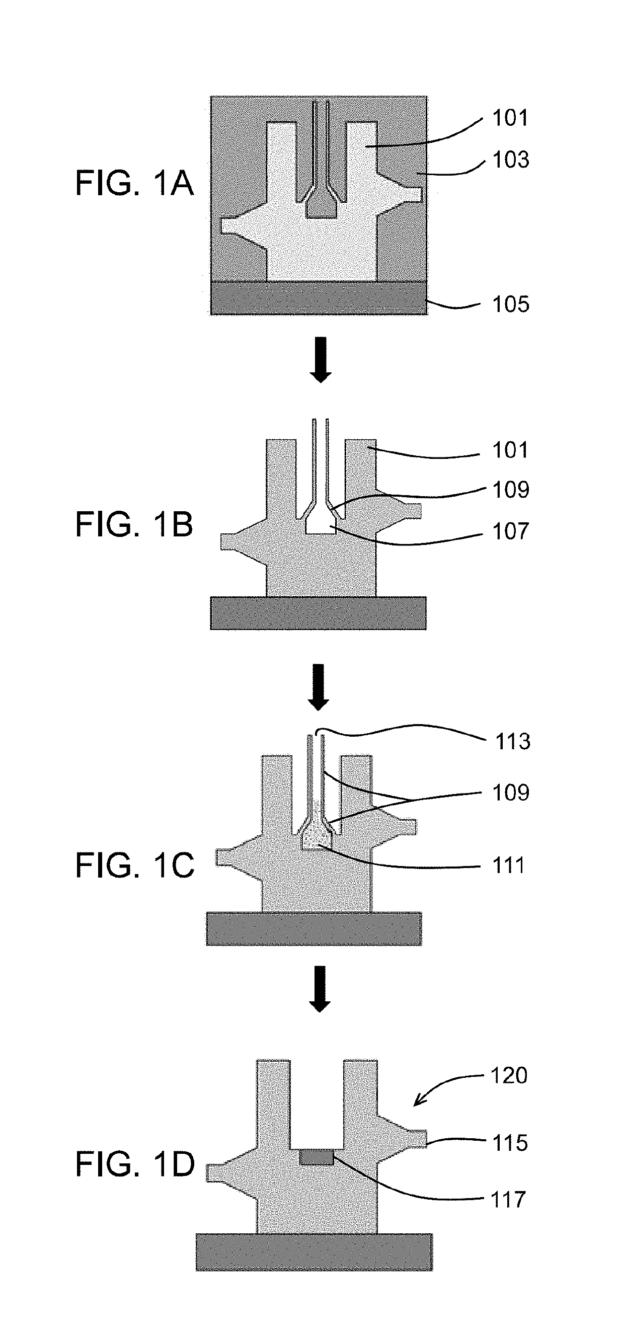
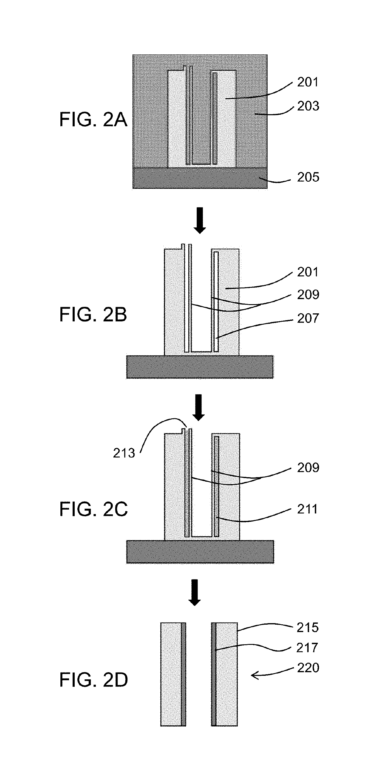
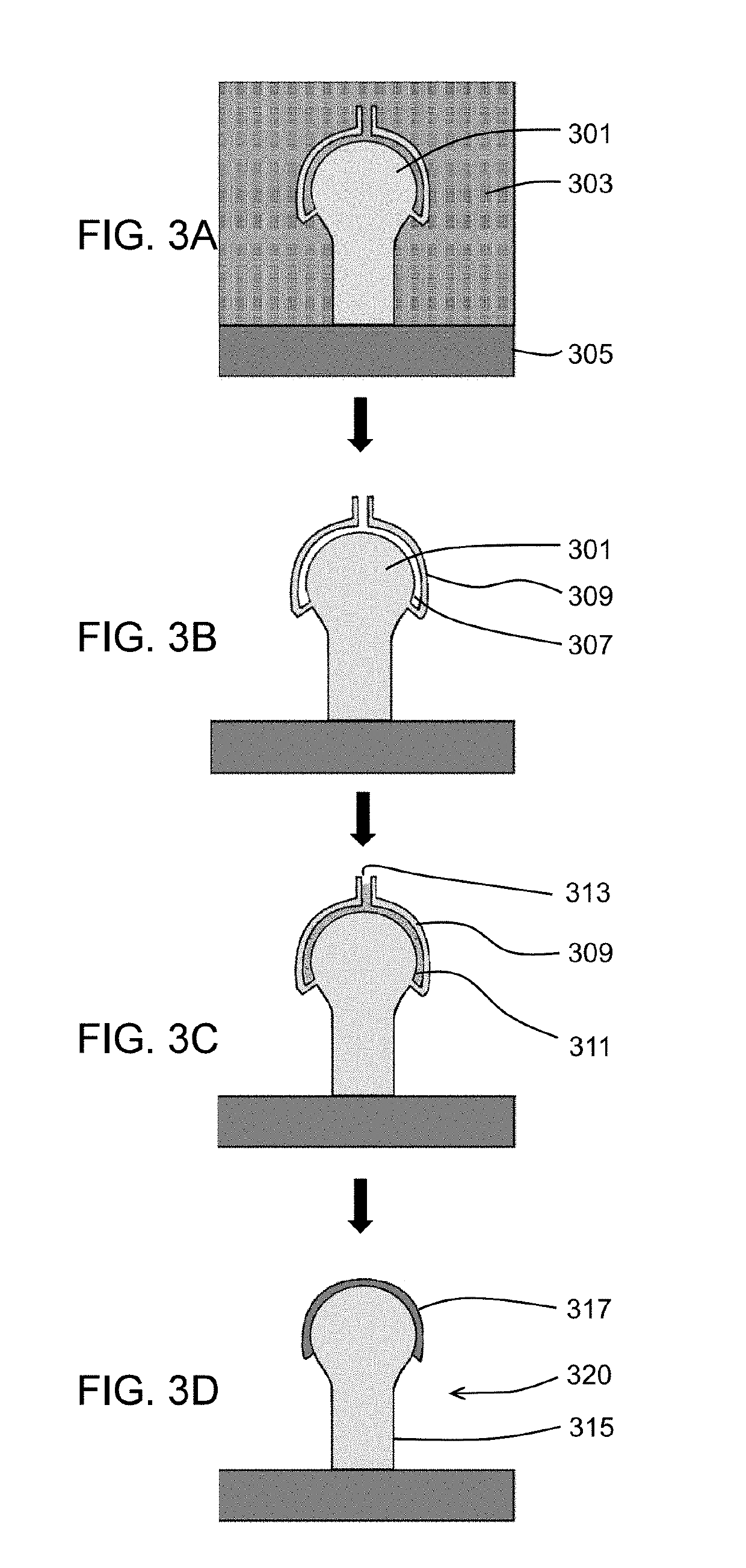
[0035]FIG. 1 shows selected schematic sections taken throughout a method of manufacture of a valve with hard facing.

[0036]FIG. 1A shows the step of forming the component body 101, here a valve body using an additive manufacturing process of laser melting / sintering. In a manner well-known to those in the art, a powder bed 103 is placed on a supporting baseplate 105, and selected areas of the powder bed as defined by a 3D product model are melted using a laser to form a solid component body. After the additive manufacture process is complete, the solid component body is surrounded by un-melted powder which is subsequently removed once the melting / sintering process is complete to leave the component body as shown in FIG. 1B. The powder is typically vacuumed away, however where the internal features are complex, the component may be manipulated to encourage the powder to flow out. For very complex parts, ultrasonic wash stations may be used. The component body is here made entirely from...


PUM

PropertyMeasurementUnit
Shapeaaaaaaaaaa

Abstract

There is provided a method of manufacture of a component from multiple materials, and a consolidated component formed thereby. The method includes the steps of forming a component body comprising a first material, the component body defining a cavity, filling at least a portion of the cavity with a second material, and performing hot isostatic pressing of the component body and second material to form a consolidated component. The process offers a reduced-complexity, reduced-part-count method of manufacture for components formed of multiple materials.

Description

CROSS-REFERENCE TO RELATED APPLICATIONS[0001]This application is based upon and claims the benefit of priority from UK Patent Application No. GB 1721769.6, filed on 22nd December 207, the entire contents of which are incorporated herein by reference.BACKGROUNDTechnical Field[0002]The present disclosure relates to a method of manufacturing a component formed of multiple materials. More specifically, it relates to a method of manufacturing a component formed of multiple materials using hot isostatic pressing.Description of the Related Art[0003]Hot isostatic pressing (HIP) is a well-known manufacturing or processing technique in which high isostatic pressure is applied to a material, typically a powder within a canister, at an elevated temperature to provide isostatic compression. Typically, this process is performed in an inert atmosphere, e.g. in an argon gas atmosphere. This has applications in reducing the porosity and increasing density of metal and ceramic materials, or in formin...

Claims


Application Information

Patent Timeline
IPC IPC(8): B22F3/15B33Y10/00B33Y40/00B22F3/105B28B1/00B29C64/153B29C64/40B23K26/354B23K26/34
CPCB22F3/15B33Y10/00B33Y40/00B22F3/1055B28B1/001B29C64/153B29C64/40B23K26/354B23K26/34B22F2003/1058B22F3/24B22F7/06B22F7/08B22F2003/242B33Y80/00B22F3/1208A61F2/3609A61F2002/3611A61F2/3094Y02P10/25B22F10/28B22F10/64B22F10/66B22F10/47B22F10/25B22F10/68B33Y40/20
Inventor BROWN, RICHARD STUART
Owner ROLLS ROYCE PLC
Why Eureka
Try Eureka