
Light shielding plate, camera unit, electronic device, and method of manufacturing light shielding plate

Pending Publication Date: 2022-11-03
TOPPAN PRINTING CO LTD
View PDF0 Cites 0 Cited by
  • Summary
  • Abstract
  • Description
  • Claims
  • Application Information

AI Technical Summary

Benefits of technology

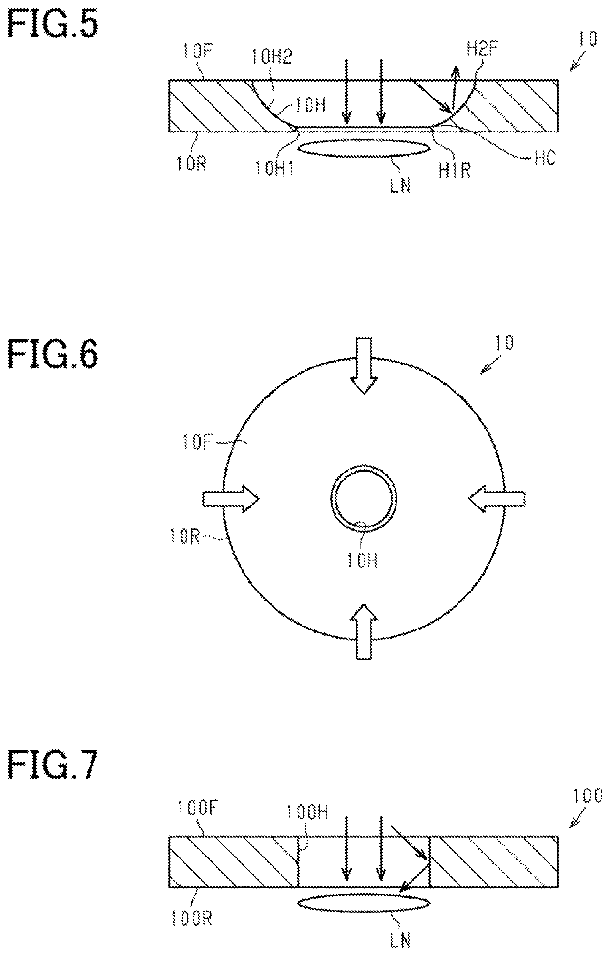
The present invention provides a light shielding plate and a method of manufacturing the plate that can prevent excessive reflected light in a captured image due to this light having passed through a hole. This is achieved by shaping the second hole portion to reflect light from its sides towards the front surface of the plate and by restricting the amount of light reflected by its first hole portion. Additionally, the patent prevents distortion of the intermediate opening to prevent excessive light from passing through at certain parts of the plate.

Problems solved by technology

Thus, the degree of light shielding by light shielding plates made of a resin is insufficient, leading to the use of light shielding plates made of metal that have better light shielding properties (see, for example, Patent Literature 2).

Method used


Image

  • Light shielding plate, camera unit, electronic device, and method of manufacturing light shielding plate
  • Light shielding plate, camera unit, electronic device, and method of manufacturing light shielding plate
  • Light shielding plate, camera unit, electronic device, and method of manufacturing light shielding plate

Examples


examples

[0086]Examples and comparative examples of the light shielding plate will be described with reference to Table 1.

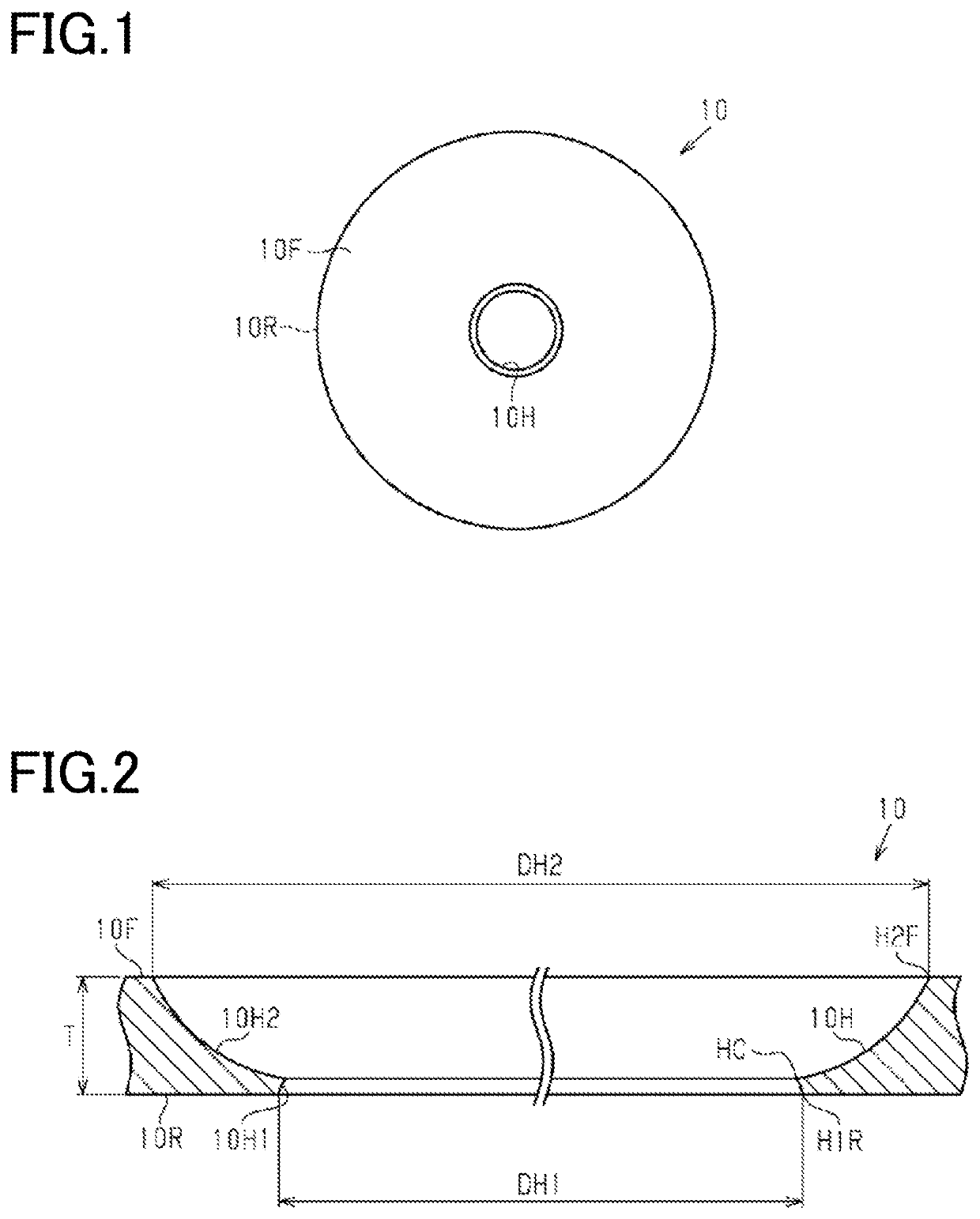
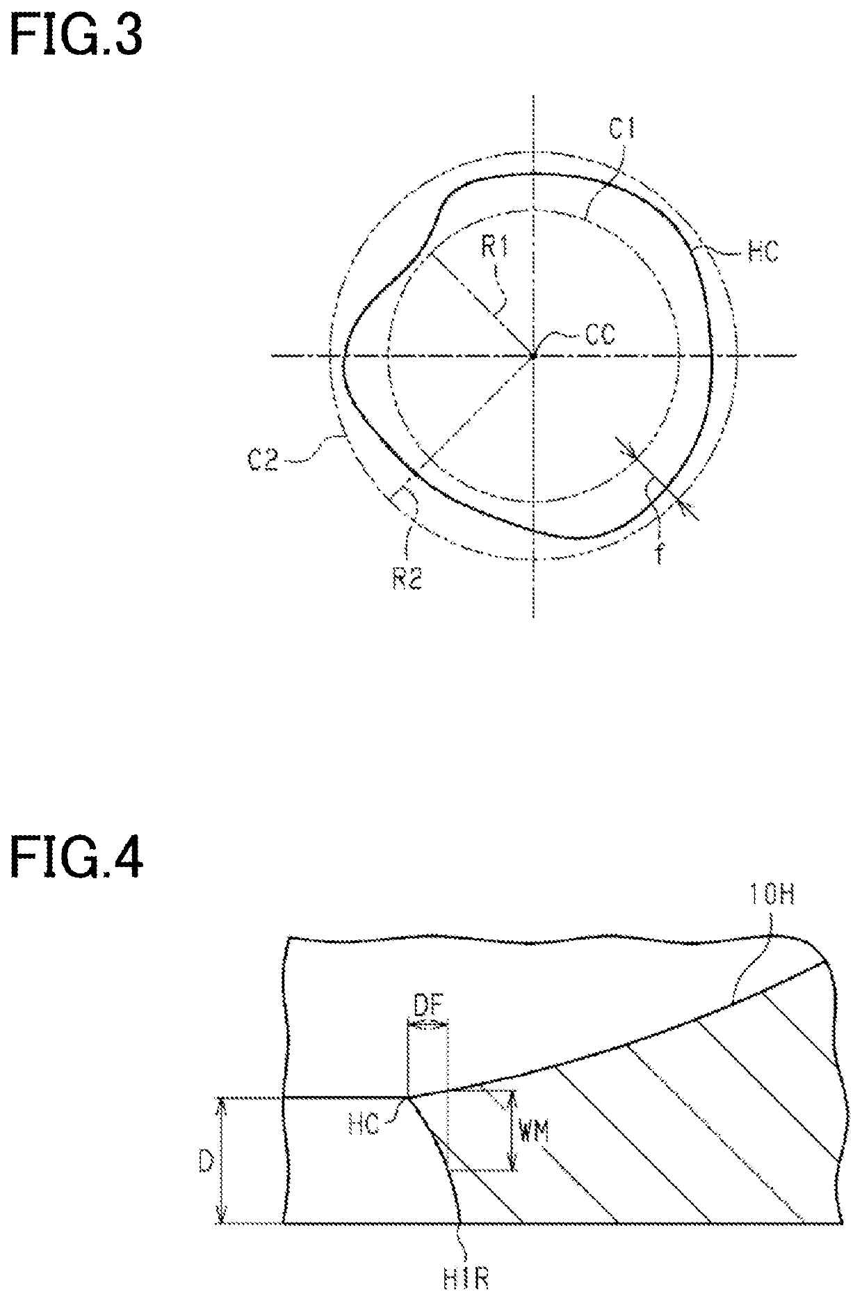
[0087]A stainless steel plate having a thickness of 25 μm was prepared. In the stainless steel plate, a plurality of first hole portions and then second hole portions connected to the respective first hole portions were formed by a roll-to-roll method. That is, after the first hole portions were formed, the second hole portions were formed. Thus, a plurality of light shielding plate precursors were formed in the stainless steel plate, each of which had a hole having a rear surface opening with a diameter of 493 μm, a front surface opening with a diameter of 680 μm, and an intermediate opening with a diameter of 490 μm.

[0088]Each of the light shielding plate precursors was connected to a non-etched region of the stainless steel plate via a part of the light shielding plate in the circumferential direction as viewed perpendicular to the front surface of the light shielding ...


PUM


Abstract

A light shielding plate includes a front surface located on a light incident side, a rear surface opposite to the front surface, and a hole passing through the light shielding plate between the front surface and the rear surface. The hole has a first hole portion and a second hole portion connected to the first hole portion at an intermediate opening thereof. The first hole portion extends from a rear surface opening on the rear surface to the intermediate opening and is shaped so as to taper from the rear surface toward the front surface. The second hole portion extends from a front surface opening on the front surface to the intermediate opening and is shaped so as to taper from the front surface toward the rear surface. The front surface opening is larger than the rear surface opening. The intermediate opening has a circularity of 3 μm or less.

Description

CROSS-REFERENCE TO RELATED PATENT APPLICATIONS[0001]This application is a continuation application filed under 35 U.S.C. § 111(a) claiming the benefit under 35 U.S.C. §§ 120 and 365(c) of International Patent Application No. PCT / JP2021 / 001872, filed on Jan. 20, 2021, which in turn claims the benefit of JP 2020-006833 filed Jan. 20, 2020 the disclosures of all which are incorporated herein by reference in its entirety.TECHNICAL FIELD[0002]The present invention relates to a light shielding plate, a camera unit including the light shielding plate, an electronic device including the camera unit, and a method of manufacturing the light shielding plate.BACKGROUND[0003]Camera units provided in electronic devices such as smartphones include a light shielding plate that functions as a diaphragm for external light. Light shielding plates made of a resin are often used because the use of a resin allows easy molding of light shielding plates having a predetermined shape (see, for example, Paten...

Claims


Application Information

Patent Timeline
IPC IPC(8): H04N5/225
CPCH04N5/2254H04N5/2252G03B17/02G03B11/04G03B9/02H04N23/55G03B30/00H04N23/57H04N23/51
Inventor NISHITSUJI, KIYOAKISHIMAMURA, SHINICHIAIZAWA, HIROYASU
Owner TOPPAN PRINTING CO LTD
Learn More