
Heat exchanger module of the type having plates comprising channels incorporating at least one fluid supply and distribution zone formed by studs

Pending Publication Date: 2022-11-10
COMMISSARIAT A LENERGIE ATOMIQUE ET AUX ENERGIES ALTERNATIVES
View PDF0 Cites 0 Cited by
  • Summary
  • Abstract
  • Description
  • Claims
  • Application Information

AI Technical Summary

Benefits of technology

The invention relates to a heat exchanger design that uses studs to ensure even distribution of fluid and to minimize pressure drop. This design allows for smaller exchanger modules to be arranged side by side, reducing the length of the piping between them. The technical effect of this design is improved efficiency and compact size.

Problems solved by technology

These shell tube exchangers have a large volume and are therefore not at all compact.
In that design, the fluid tight vessel acts as a collector for the gas circuit and the sizing of the heat exchanger module is driven first and foremost by the gas, because, of the two fluids, that is the least effective at transferring heat.
Whereas the size of the exchange pattern of the gas circulation channels is strictly dependently on the thermos-hydraulic performance constraints, the size of the liquid metal circulation channels needs to take into consideration the risks of blockage associated with the circulation of the liquid metal, and this limits the minimum cross section of the circulation channels for this liquid.
In operation, the structures supplying and collecting the liquid metal, which consist of the headers and of the distribution pipework, may be subjected to compressive loadings at high pressure and without special precautions this could lead to damage by buckling with creep.
This configuration may lead to a nonuniform distribution of the liquid metal in the channels within each exchanger module, which may be detrimental on the one had to the overall thermal efficiency of the exchanger and on the other hand to the thermomechanical integrity of the structures of the exchanger.
Poor flow distribution is characterized by certain heat exchange channels being oversupplied at the expense of certain others.
This solution therefore offers the prime advantage of quickly adding pressure drops to the bundle, although this may also become a disadvantage.

Method used


Image

  • Heat exchanger module of the type having plates comprising channels incorporating at least one fluid supply and distribution zone formed by studs
  • Heat exchanger module of the type having plates comprising channels incorporating at least one fluid supply and distribution zone formed by studs
  • Heat exchanger module of the type having plates comprising channels incorporating at least one fluid supply and distribution zone formed by studs

Examples


Embodiment Construction

[0101]For the sake of clarity, the same elements are denoted by the same numerical references according to the prior art and according to the invention.

[0102]It is emphasized that throughout the application, the terms “inlet”, “outlet”, “upstream”, “downstream” are to be understood in relation to the direction in which the fluid concerns circulates in the heat exchange module according to the invention.

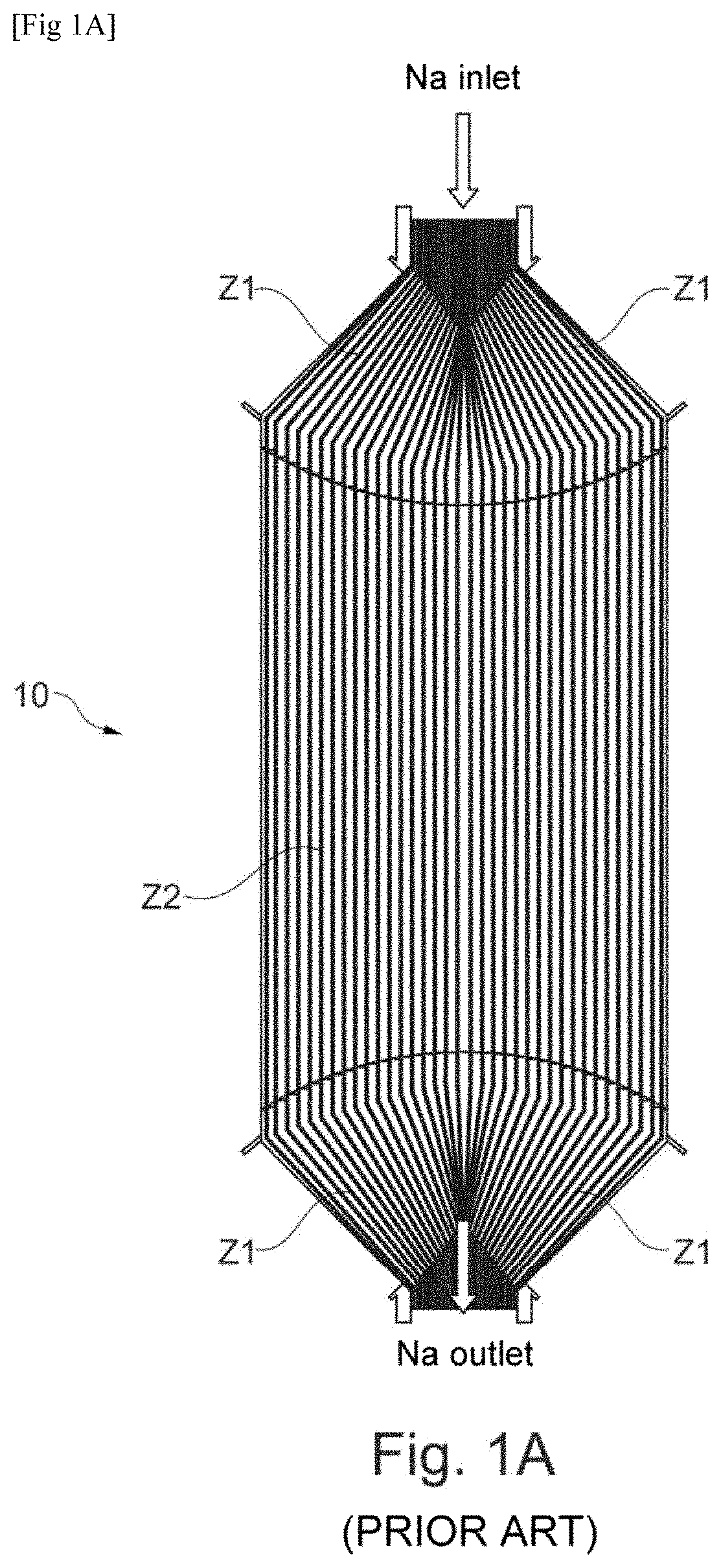
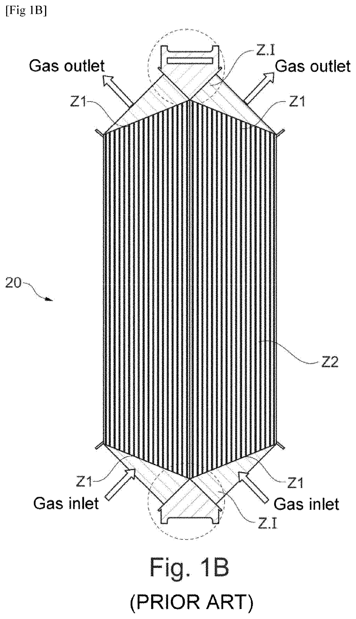
[0103]FIGS. 1A and 1B relating to the prior art were already commentated on in the preamble. They will therefore not be commented upon hereafter.

[0104]FIGS. 2 and 3 depict an embodiment of a heat exchanger module according to the invention with two fluid circuits, which is employed by way of example for an exchange between liquid sodium (Na) and nitrogen (N2).

[0105]The module 1 is made up of an alternating stack of metal plates 10, 20 assembled with one another by the fusion welding, preferably using an HIP technique, or produced by additive manufacturing.

[0106]As visible in these fig...


PUM


Abstract

A heat exchanger module having at least two fluid circuits, of longitudinal axis including a stack of plates, defining at least two fluid circuits, at least a part of the plates each including fluid circulation channels, the channels of at least one of the two circuits, referred to as first circuit, having at least one fluid supply and distribution zone for supplying and distributing fluid from outside the stack, forming a fluid pre-header, in which zone the channels are delimited by studs distributed over the surface of the plate; an exchange zone continuous with the pre-header and wherein the channels are each delimited by a groove separated from one another by a rib and extending along the longitudinal axis.

Description

TECHNICAL FIELD[0001]The present invention relates to a heat exchanger module with a stack of metal plates, incorporating at least two fluid circuits.[0002]The invention relates more particularly to the creation of a normal type of heat exchanger module for improving the uniformity of the distribution of the various internal fluid circulation channels while at the same time ensuring good thermal efficiency and satisfactory thermal mechanical loading, and doing so without detriment to the compactness of the module.[0003]Known heat exchangers comprise either at least two circuits with internal fluid circulation channels. In exchangers having one single circuit, the exchangers of heat are performed between the circuit and a surround fluid in which it is immersed. In exchangers having at least two fluid circuits, the exchanges of heat are between the two fluid circuits.[0004]Chemical reactors which perform a continuous process whereby a small quantity of coreactants are injected simulta...

Claims


Application Information

Patent Timeline
IPC IPC(8): F28D9/00F28F9/02
CPCF28D9/0037F28F9/0217F28D9/005F28F2275/04F28F2275/061F28F2275/062F28F3/08F28F9/00F28D9/0043F28F9/026F28F3/02F28D2021/0054F28D9/0006F28F13/06G21D1/006Y02E30/30
Inventor JEANNINGROS, XAVIERGROSSE, JULIENSERRE, JULIENVINCENT, SÉBASTIENCACHON, LIONEL
Owner COMMISSARIAT A LENERGIE ATOMIQUE ET AUX ENERGIES ALTERNATIVES
Learn More