Supercharge Your Innovation With Domain-Expert AI Agents!

Vehicular radar auxiliary jig, vehicular radar mounting method and vehicular radar detecting method

a technology of vehicular radar and auxiliary jig, which is applied in the direction of instruments, measurement devices, and using reradiation to achieve the effect of convenient operation, simple and cheap

Pending Publication Date: 2022-11-10
TUNG THIH ELECTRONICS
View PDF0 Cites 0 Cited by
  • Summary
  • Abstract
  • Description
  • Claims
  • Application Information

AI Technical Summary

Benefits of technology

The present invention provides a vehicular radar auxiliary jig and a vehicular radar mounting method that allows for easy and accurate mounting of the radar component on a vehicle. The jig includes an angle plotting board with a pre-configured angle, which ensures that the radar component is mounted at the precise location on the vehicle. Additionally, the jig fixes the distance between the vehicle and the radar component, which ensures reliable testing in accordance with the radar test program. The method of detecting radar using this invention is simpler, easier and less expensive than conventional methods.

Problems solved by technology

However, the vehicle will fail the test even if the angle, height or location of the radar installed is just slightly wrong.
However, a problem that remains unsolved is how to precisely adjust the distance, angle and height of the radar reflecting board relative to a target vehicle in order to position the radar reflecting board at a predetermined target location and thereby render the collected reflecting wave data accurate.
The CSC-TOOL of Hella Gutmann Solutions GmbH adjusts the location and angle of the radar reflecting board relative to a target vehicle semi-automatically; however, it and its applicable software are expensive.
Manual adjustment not only relies upon technicians' experience but is also predisposed to inaccuracy of the data collected.

Method used


Image

  • Vehicular radar auxiliary jig, vehicular radar mounting method and vehicular radar detecting method
  • Vehicular radar auxiliary jig, vehicular radar mounting method and vehicular radar detecting method
  • Vehicular radar auxiliary jig, vehicular radar mounting method and vehicular radar detecting method

Examples


Embodiment Construction

[0021]To facilitate understanding of the object, characteristics and effects of this present disclosure, embodiments together with the attached drawings for the detailed description of the present disclosure are provided.

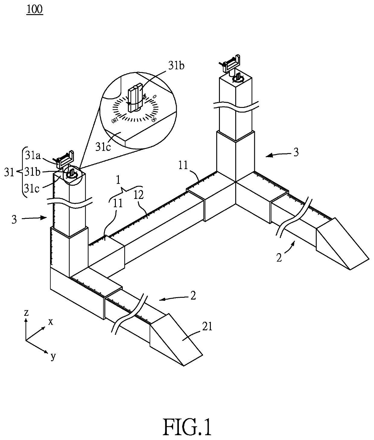
[0022]As shown in FIG. 1, in an embodiment of the present disclosure, a vehicular radar auxiliary jig 100 comprises a transverse extensible bar 1, two longitudinal extensible bars 2 and two upright bars 3.

[0023]The transverse extensible bar 1 can be extended adjustably in a transverse direction (X axis of FIG. 1). In this embodiment, the transverse extensible bar 1 comprises two outer bars 11 and an inner bar 12 telescopically connected between the two outer bars 11. The total length of the transverse extensible bar 1 can be adjusted by adjusting the extent to which the inner bar 12 is slid within the outer bars 11. However, the present disclosure is not limited thereto, and thus the transverse extensible bar 1 may be any conventional extensible bar, such as a combi...


PUM


Abstract

A vehicular radar auxiliary jig includes a transverse extensible bar, two longitudinal extensible bars and two upright bars. The longitudinal extensible bars are perpendicularly connected to two ends of the transverse extensible bar, respectively. One end of each longitudinal extensible bar is positioned distal to the transverse extensible bar and provided with a tire securing portion. The upright bars are perpendicularly connected to two ends of the transverse extensible bar and are perpendicular to the longitudinal extensible bars, respectively. One end of each upright bar is positioned distal to the transverse extensible bar and provided with a mounting portion, thereby connecting to an electromagnetic wave component. A vehicular radar mounting method and vehicular radar detecting method, each using the vehicular radar auxiliary jig, are provided. The vehicular radar auxiliary jig, vehicular radar mounting method and vehicular radar detecting method enable a vehicular radar to be mounted and tested efficiently.

Description

CROSS-REFERENCE TO RELATED APPLICATION[0001]This non-provisional application claims priority under 35 U.S.C. § 119(a) on Patent Application No(s).110116366 filed in Taiwan, R.O.C. on May 6, 2021, the entire contents of which are hereby incorporated by reference.BACKGROUND OF THE INVENTION1. Field of the Invention[0002]The present disclosure relates to an auxiliary jig, component mounting method and detecting method, and in particular to a vehicular radar auxiliary jig, vehicular radar mounting method and vehicular radar detecting method.2. Description of the Related Art[0003]Radar (radio detection and ranging), i.e., wireless detection and ranging technology, entails emitting radio waves in fixed directions into free space. The intercepted radio waves that hit a target in the free space are reflected back, received and calculated to figure out the location, height and speed of the target and delve into the shape of the target. In recent years, vehicles are increasingly likely to be ...

Claims


Application Information

Patent Timeline
IPC IPC(8): G01S7/02G01S13/931
CPCG01S7/027G01S13/931G01S2013/93271G01S2013/93272G01S7/02G01S7/40G01S7/4026G01S7/4086
Inventor KUO, HSUAN-YIWANG, CHENG-CHUAN
Owner TUNG THIH ELECTRONICS
Features
  • R&D
  • Intellectual Property
  • Life Sciences
  • Materials
  • Tech Scout
  • Unparalleled Data Quality
  • Higher Quality Content
  • 60% Fewer Hallucinations
Learn More