Eureka AIR delivers breakthrough ideas for toughest innovation challenges, trusted by R&D personnel around the world.

Device for validating the axis linearity and/or the positioning accuracy of a displacement mechanism for a radiation detector and associated method of practice

Pending Publication Date: 2022-11-10
LAP LASER APPLIKATIONEN
View PDF0 Cites 0 Cited by
  • Summary
  • Abstract
  • Description
  • Claims
  • Application Information

AI Technical Summary

Benefits of technology

The invention is a device and method for validating the position and linearity of a radiation detector in a magnetic resonance tomograph (MRT) during treatment. The device includes a tactile sensor element that can detect the position of a standard element in real-conditions, even with an active magnetic field. The device can be easily brought onto the patient couch of the MRT and performs its validation with no disruptions caused by the magnetic field. The invention allows for a reliable validation of the treatment beam's position and intensity, improving the accuracy of the treatment process. The device is cost-effective and can be easily integrated into the MRT system. The tactile sensor element and standard element can be made of non-ferromagnetic materials, such as ceramic or aluminum, and can be driven up to when the device is inside or outside of the MRT's magnetic field. The tactile sensor element can be positioned on the displacement mechanism of the radiation detector, ensuring a secure validation.

Problems solved by technology

During the movement of the radiation detector and in particular of the carriage carrying it along the respective movement axis, however, undesired deviations can occur.
Such systems, however, have multiple disadvantages.
With such an external system, the axis linearity of the radiation detector cannot be established under real conditions.
This is because, on the one hand, the water phantom can impair the measurement in its water-filled state.
Such a positioning of the water phantom within the MRT, however, prevents a measurement with such an external measurement system for reasons of space.
In addition, the strong magnetic field impairs the external measurement system.
Designing the parts of the external measurement system to be MR-suitable is complex and expensive.

Method used


Image

  • Device for validating the axis linearity and/or the positioning accuracy of a displacement mechanism for a radiation detector and associated method of practice
  • Device for validating the axis linearity and/or the positioning accuracy of a displacement mechanism for a radiation detector and associated method of practice
  • Device for validating the axis linearity and/or the positioning accuracy of a displacement mechanism for a radiation detector and associated method of practice

Examples


first embodiment

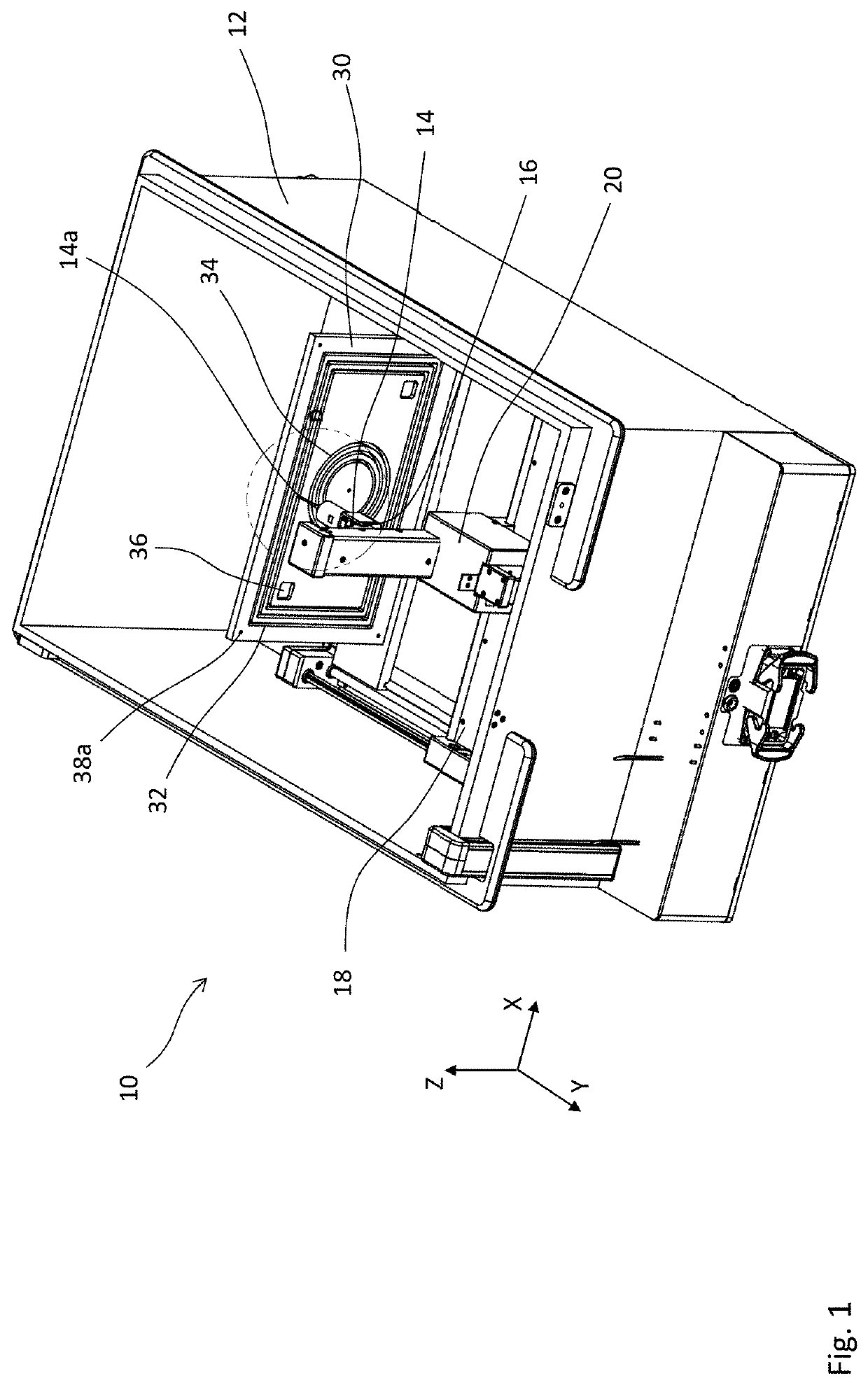
[0035]In FIG. 1, the device according to the invention can be seen. The device 10 shows a water phantom comprising a container 12 which can be filled with water. A tactile sensor element 14 with a sensor head 14a is arranged within the container 12. The sensor element 14 can be displaced via a displacement mechanism 16, 18, 20 which comprises three carriages with which the sensor element 14 can be displaced along the three spatial axes X, Y, and Z which are orthogonal to each other. The sensor element 14 is thus displaceable along the Z-axis via a first carriage 16, along the Y-axis via a second carriage 18, and along the X-axis via a third carriage 20. The first carriage 16 runs on a first rail 16a, the second carriage 18 runs on a second rail 18a, and the third carriage 20 runs on a third rail 20a (see FIG. 3). The rails 16a, 18a, 20a all run orthogonally to one another, each along one of the three spatial directions. The three carriages 16, 18, 20 and the rails 16a, 18a, 20a of t...

second embodiment

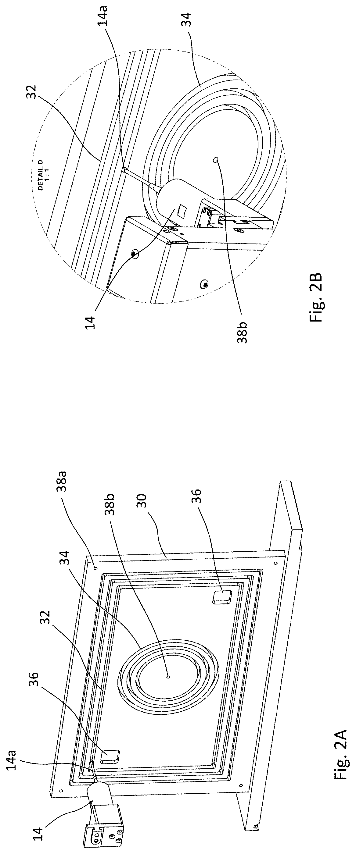
[0042]With the device according to FIGS. 1 and 2, the axis position or respectively axis linearity of the radiation detector can thus be validated along all three spatial axes in a particularly simple and reliable manner under real conditions. The same applies to the second embodiment explained in the following.

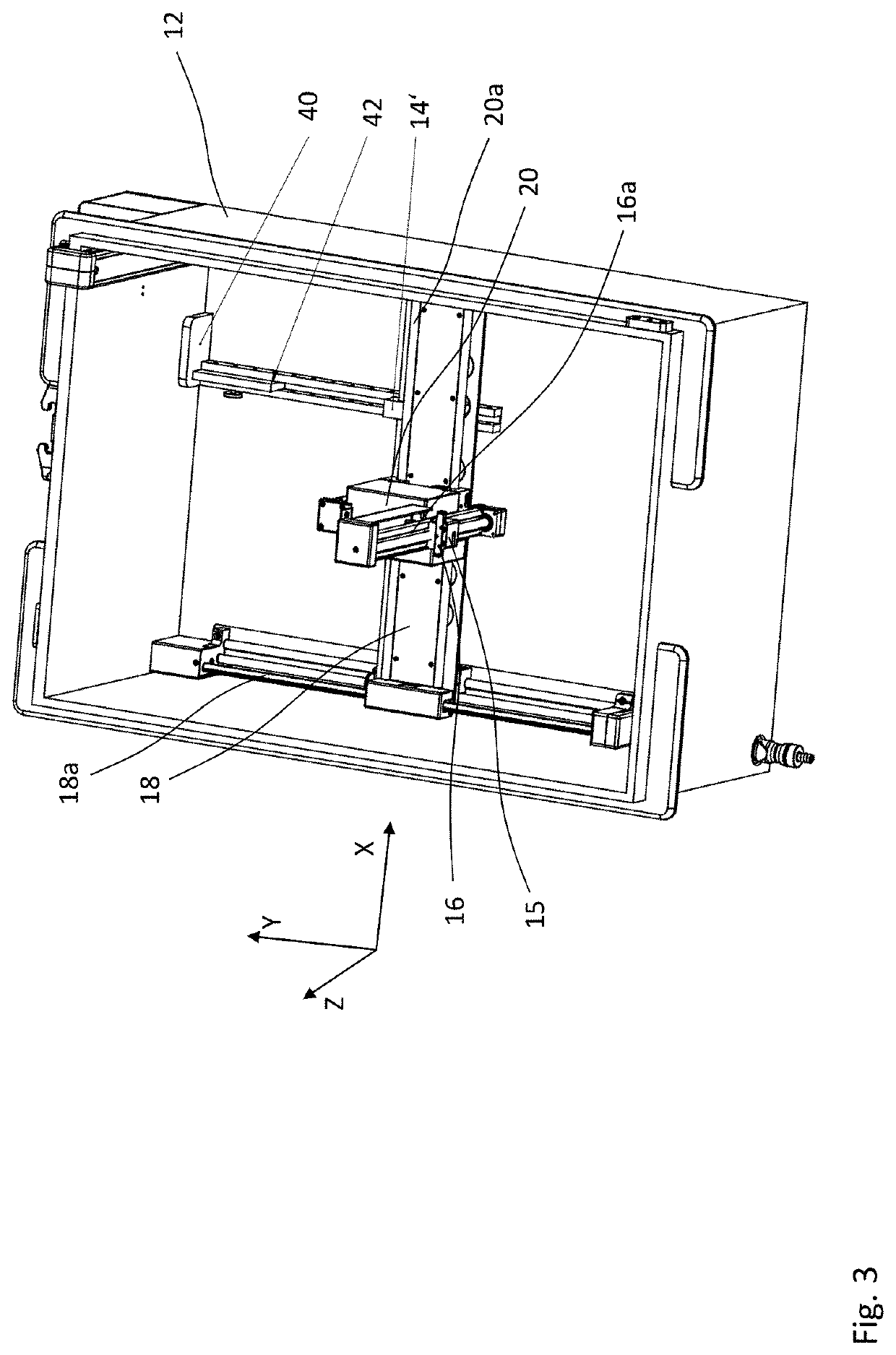
[0043]FIGS. 3 to 6 show another embodiment of a device according to the invention which differs from the one previously explained in that, instead of the test plate 30, precision gauge blocks 42, 44, 46 are provided as standard elements, which can consist in particular of ceramic and can thus be MR-suitable.

[0044]FIG. 3 shows a tactile sensor element 14′ which is arranged on the second carriage 18 and is thus movable along the Y-axis. A gauge block guide 40 which receives a gauge block 42 in FIG. 3 extends along the Y-axis. In this view, the receiving element 15 already discussed previously can be seen on the first rail 16, which element serves to receive the radiation detect...


PUM


Abstract

A method for validating the axis linearity of a displacement mechanism for a radiation detector configured to detect high-energy radiation emitted by an irradiation device comprises providing a container configured to receive a liquid. A tactile sensor and a standard element are positioned within the container configured for receiving the liquid. A displacement mechanism is structured to displace at least one of: (1) the tactile sensor; and (2) the standard element along at least one spatial axis. The tactile sensor is used to tactilely detect the standard element.

Description

CROSS REFERENCE TO RELATED INVENTION[0001]This application is based upon and claims priority to, under relevant sections of 35 U.S.C. § 119, German Patent Application No. 10 2021 111 815.8, filed May 6, 2021, the entire contents of which are hereby incorporated by reference.TECHNOLOGICAL FIELD[0002]This disclosure relates to a method and a device for validating the axis linearity and / or the positioning accuracy of a displacement mechanism for a radiation detector, which is configured for detecting high-energy radiation emitted by an irradiation device.BACKGROUND[0003]In the field of medicine, irradiation devices are employed to treat malignant tissue. For example, highly accelerated particle radiation generated by means of a linear particle accelerator (LINAC) or respectively electromagnetic radiation is aimed at the tissue to be treated. Such a radiation treatment must be performed very precisely both with regard to the location of impact of the radiation and with regard to the int...

Claims


Application Information

Patent Timeline
IPC IPC(8): G01T7/00G01B21/24
CPCG01T7/005G01B21/24A61N5/1075
Inventor BRUNK, MARKUSBOJARA, DANIEL
Owner LAP LASER APPLIKATIONEN
Why Eureka
Eureka Blog
Learn More