
Press and methods for cutting and folding a safety razor to form a 2-blade system for a razor head, and assembly

Pending Publication Date: 2022-11-17
GLENN II ROBERT J
View PDF9 Cites 0 Cited by
  • Summary
  • Abstract
  • Description
  • Claims
  • Application Information

AI Technical Summary

Benefits of technology

The patent describes a shaving head assembly that combines the features of a double-edged safety razor with a multi-blade cartridge shave. The assembly includes a shaving head front and a shaving head back component, a replaceable handle, and a blade loading device. The device safely breaks the blade into two parts and aligns them in position for a two-bladed cartridge shave head that is reusable. The assembly allows for easy loading of blade and shaving with both cutting edges of the double-edged safety razor blade simultaneously, providing the quality and economic advantages of a double-edged safety razor shave with the usability of a multi-blade cartridge shave.

Problems solved by technology

These products have the disadvantage of requiring more skill and practice to achieve a safe and close shave over multiple blade cartridge style razor designs.
Multiple blade razors have the disadvantage of being expensive due to their complexity of design.
Conventional disposable razors and shaving razors with replaceable cartridges are discarded and their plastic and metal parts end up in landfills, contributing to a global waste management problem.

Method used


Image

  • Press and methods for cutting and folding a safety razor to form a 2-blade system for a razor head, and assembly
  • Press and methods for cutting and folding a safety razor to form a 2-blade system for a razor head, and assembly
  • Press and methods for cutting and folding a safety razor to form a 2-blade system for a razor head, and assembly

Examples


Embodiment Construction

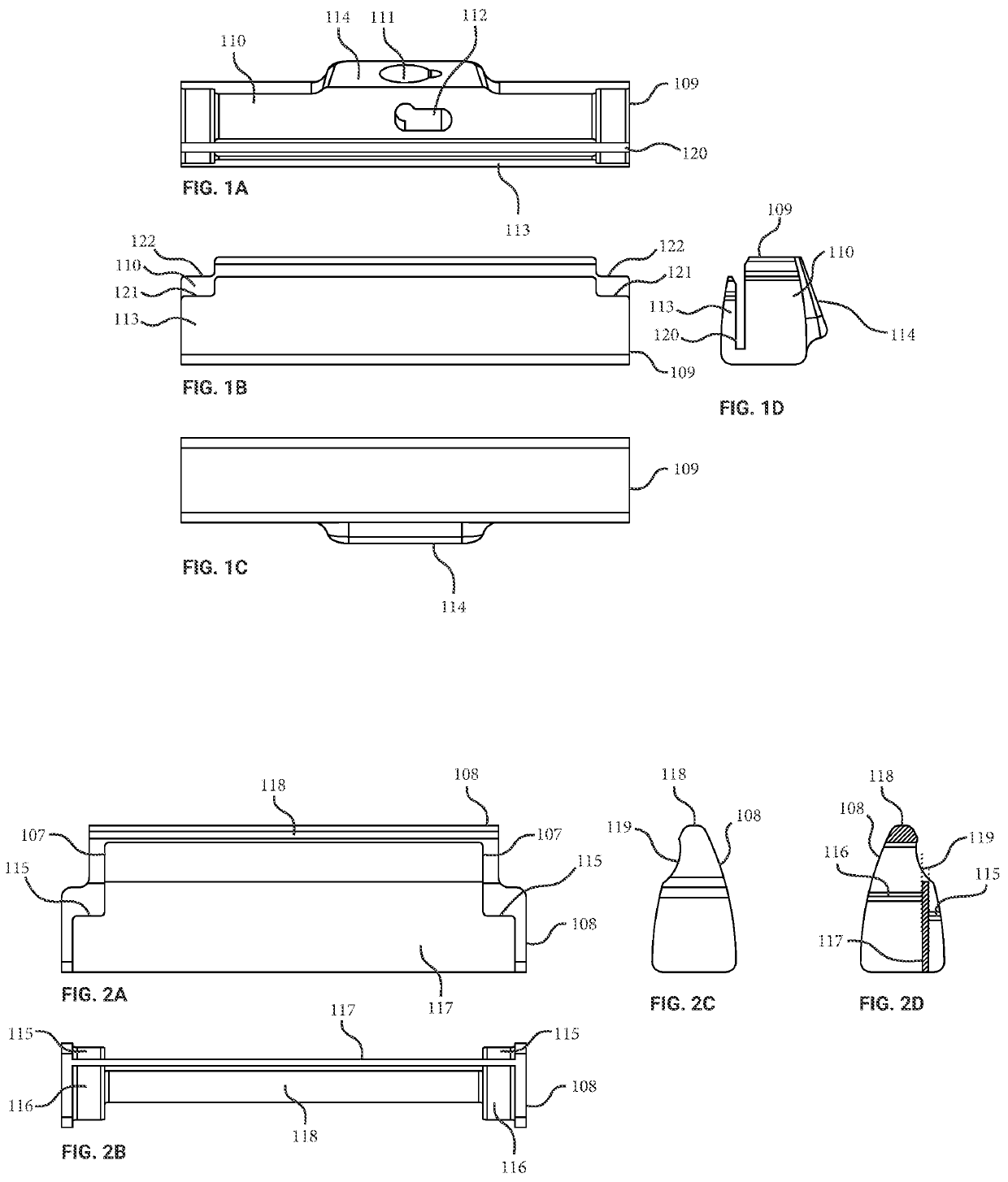
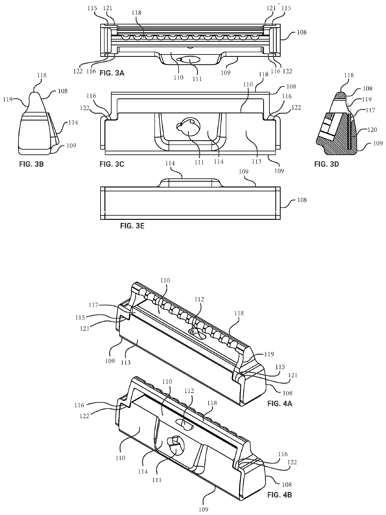
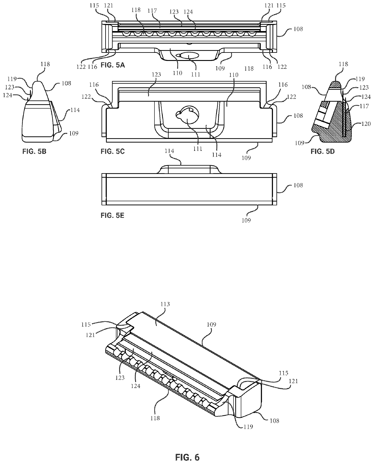
[0072]Referring to FIGS. 1A-1D, there is shown various views of the shaving head back component 109. The shaving head back component refers to the component that is attached to the handle of a shaving razor. Generally, back refers to an area or direction toward the handle, and front refers to an area or direction away from the handle toward a shaving interface with a user's skin. An angular locating surface 114 is positioned normal to a handle insertion pocket 111 giving the operator a visual cue for the proper insertion of multiple handle options. An undercut pocket 112 is located in a position that locks the handle into its operating position by way of an insertion and retention mechanism shown in FIGS. 10A, 10B, and 11. Notch details 121 and 122 are relief details that interface with the shaving head front component 108 shown in FIGS. 2A-2D. The shaving head front component refers to the component that is inserted into the shaving head back component 109 when the razor is loaded ...


PUM


Abstract

A shaving head that doubles as breaking mechanism to break a safety razor blade into two pieces to form a 2-blade shaving razor. The shaving head includes a front component having a retention guide, a first position stop and a second position stop at a distance offset from the first position stop. The shaving head further includes a back component having a blade slot configured to receive a first blade portion and a second blade portion formed from breaking a double-edge safety razor blade such that the first blade portion has a different width compared to the second blade portion. The retention guide is configured to retain the first blade portion and the second blade portion in the blade slot responsive to the retention guide being at least partially inserted into the blade slot. The sharp shaving edges once installed form a shaving angle between 5 and 30 degrees, where the shaving angle is determined by where the blade is broken.

Description

CROSS-REFERENCE TO RELATED APPLICATION[0001]This application claims priority to and the benefit of co-pending U.S. Provisional Patent Application Ser. No. 63 / 138,434, filed Jan. 16, 2021, entitled, “Press and Methods for Cutting and Folding a Safety Razor to Form a 2-blade System for a Razor Head, and Assembly,” and co-pending U.S. Provisional Patent Application Serial No. 63 / 232,565, filed Aug. 12, 2021, entitled “Press and Methods for Cutting and Folding a Safety Razor to Form a 2-blade System for a Razor Head, and Assembly,” both of which are incorporated herein in their respective entireties.BACKGROUND OF THE INVENTION[0002]Shaving razors, typically called safety razors, have been used for shaving for over a century. They typically utilize a replaceable double-edge safety razor blade in a configuration that allows a user to shave with one side of the blade at a time for a single blade shave. These products have the advantage of using a replaceable blade that is inexpensive when ...

Claims


Application Information

Patent Timeline
IPC IPC(8): B26B21/52
CPCB26B21/521B26B21/14B21D53/645B21D5/02B26B21/4012B26B21/4068B26B21/18
Inventor GLENN, II, ROBERT J.
Owner GLENN II ROBERT J
Learn More