Service method for automated banking machine

a service method and automated banking technology, applied in automatic teller machines, atm details, instruments, etc., can solve the problems of increasing the space required for an atm installation, requiring significant space for servicing an atm, and unrealistically removing components from the atm enclosure, etc., to achieve the effect of being serviceabl

Inactive Publication Date: 2000-01-04
DIEBOLD NIXDORF
View PDF13 Cites 192 Cited by
  • Summary
  • Abstract
  • Description
  • Claims
  • Application Information

AI Technical Summary

Benefits of technology

It is an object of the present invention to provide an automated teller machine that is more readily serviceable.

Problems solved by technology

Another problem that has occurred in the prior art is that when an ATM is installed within a facility, there must not only be room for the device, but there must also be provided sufficient area surrounding the machine for servicing.
Significant space is also required for servicing an ATM because it is often unrealistic to service or repair components within the tight confines of the ATM enclosure.
Such chassis often occupy a substantial part of the overall width of the ATM enclosure.
The requirement of providing access space for servicing increases the amount of space required for an ATM installation.
Likewise, lobby unit ATMs cannot be generally mounted flush against a wall or in line with other self-service machines.
This means that the lobby ATM must be generally freestanding and requires surrounding unproductive floor space.
In addition, the fact that persons could gain access to several sides of a lobby ATM unit increases the risk of attack by burglars as well as increases the opportunities for theft of the entire unit.

Method used


Image

  • Service method for automated banking machine
  • Service method for automated banking machine
  • Service method for automated banking machine

Examples


Embodiment Construction

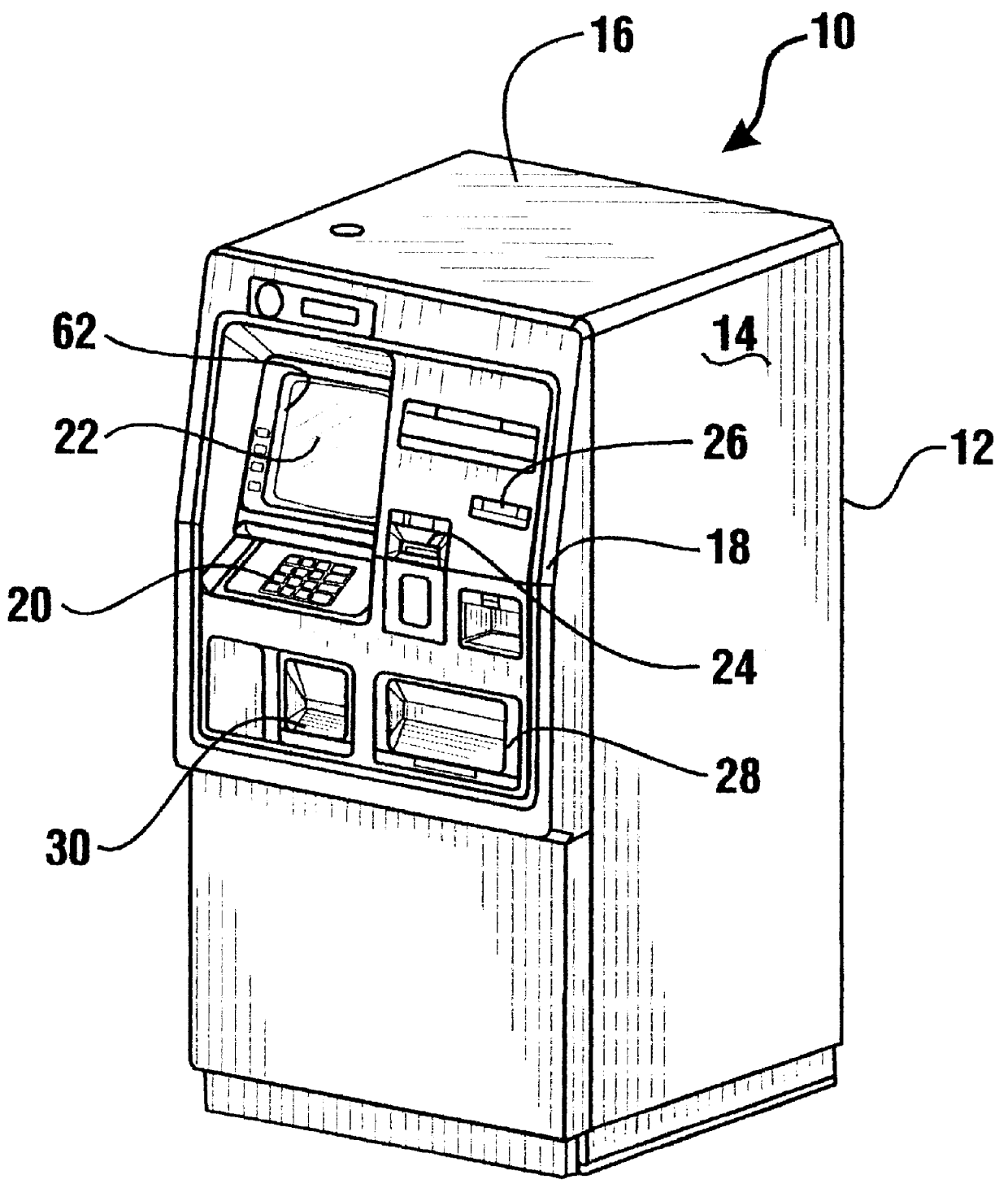
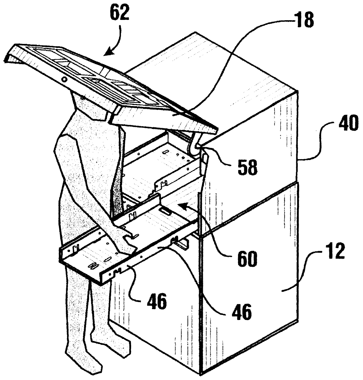
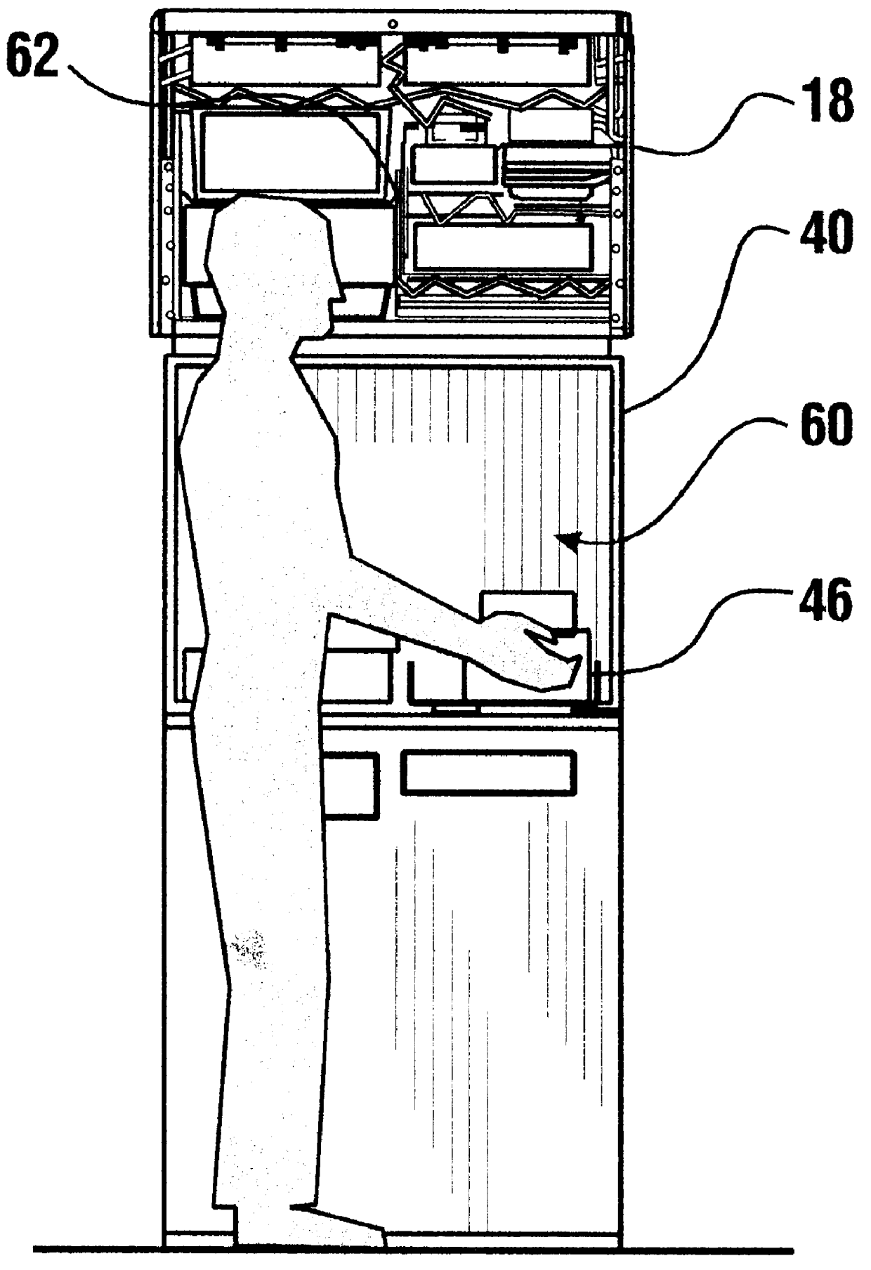
Referring now to the drawings and particularly to FIG. 1, there is shown therein an automated teller machine generally indicated 10. The ATM has a housing or enclosure 12 which includes a pair of spaced side walls 14 and a top wall 16. The ATM 10 further includes a front fascia panel 18 which includes the customer interface for the machine. Fascia panel 18 has extending thereon or accessible therethrough a keyboard 20, a monitor screen 22, a customer card accepting slot 24 and a receipt delivery opening 26. The ATM further includes a cash delivery door 28 as well as a deposit accepting opening 30. Of course, the fascia panel may have other openings and / or components accessible therethrough, such as a camera or a supply of depository envelopes.

The ATM 10 is a lobby installed unit which is freestanding within the confines of a bank, grocery store or other facility where customers may wish to conduct financial transactions or other types of transactions on an automated basis.

As best sh...


PUM


Abstract

An automated banking machine (10) includes a housing (12) with a top assembly (40). Rollout trays (46) are mounted in the top assembly and have serviceable components supported thereon. Servicing is accomplished through method steps which include opening a service door (18) and separately extending and retracting the trays to render the serviceable components thereon accessible for servicing.

Description

This invention relates to automated teller machines. Specifically, this invention relates to a method of servicing an automated teller machine which includes serviceable components supported on independently movable trays arranged in generally side by side relation.Automated teller machines (ATMs) are known in the prior art. Customers of financial institutions may perform banking transactions, make inquiries concerning the status of their accounts, pay bills and obtain other banking services using automated teller machines. Typically the customer uses a magnetically encoded card that is inserted into the machine. The customer also inputs a personal identification number that allows the automated teller machine to verify the customer's identity. After the customer has conducted their transactions, the customer's card is returned along with one or more receipts which document the transactions conducted.There are a number of different types of automated teller machines (ATMs). Some aut...

Claims


Application Information

Patent Timeline
Patent Type & Authority Patents(United States)
IPC IPC(8): G07F19/00
CPCG07F19/20G07F19/201G07F19/205
Inventor RAMACHANDRAN, NATARAJANSEDLOCK, GERALD T.LEWIS, KIM RAYMONDPRICE, III, CHARLES D.LUTE, JR., RICHARD CALVIN
Owner DIEBOLD NIXDORF
Why Eureka
Try Eureka