
Generalized procedure for the calibration of switched capacitor gain stages

a technology of switching capacitors and gain stages, applied in the direction of frequency analysis, amplifiers, amplifiers using switched capacitors, etc., can solve the problems of affecting the accuracy of the above method

Inactive Publication Date: 2000-01-04
PMC-SIERRA
View PDF5 Cites 37 Cited by
  • Summary
  • Abstract
  • Description
  • Claims
  • Application Information

AI Technical Summary

Problems solved by technology

While relatively precise gains can be obtained with switched-capacitor gain stages, their accuracy is limited to about 1 part in 1000 due to mismatches in the capacitor ratios.
This process is both expensive and does not correct for possible component drifts due to time and temperature.
The above method suffers from two main limitations.
Secondly, the input capacitor cannot be trimmed while monitoring the operational amplifier's output.
The combination of these two requirements increases the required die area and trim line leading to a less than optimal solution.

Method used


Image

  • Generalized procedure for the calibration of switched capacitor gain stages
  • Generalized procedure for the calibration of switched capacitor gain stages
  • Generalized procedure for the calibration of switched capacitor gain stages

Examples


Embodiment Construction

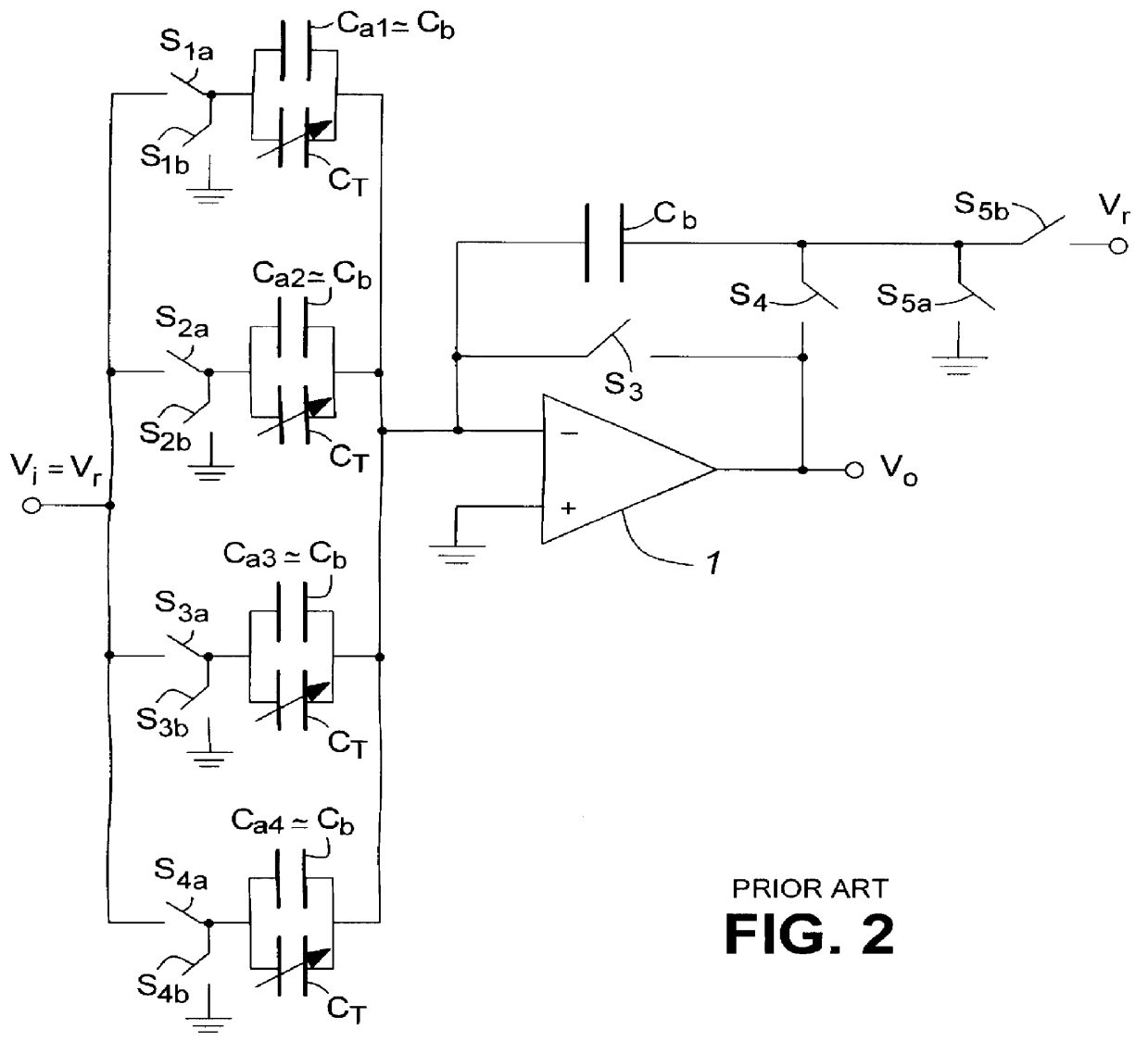
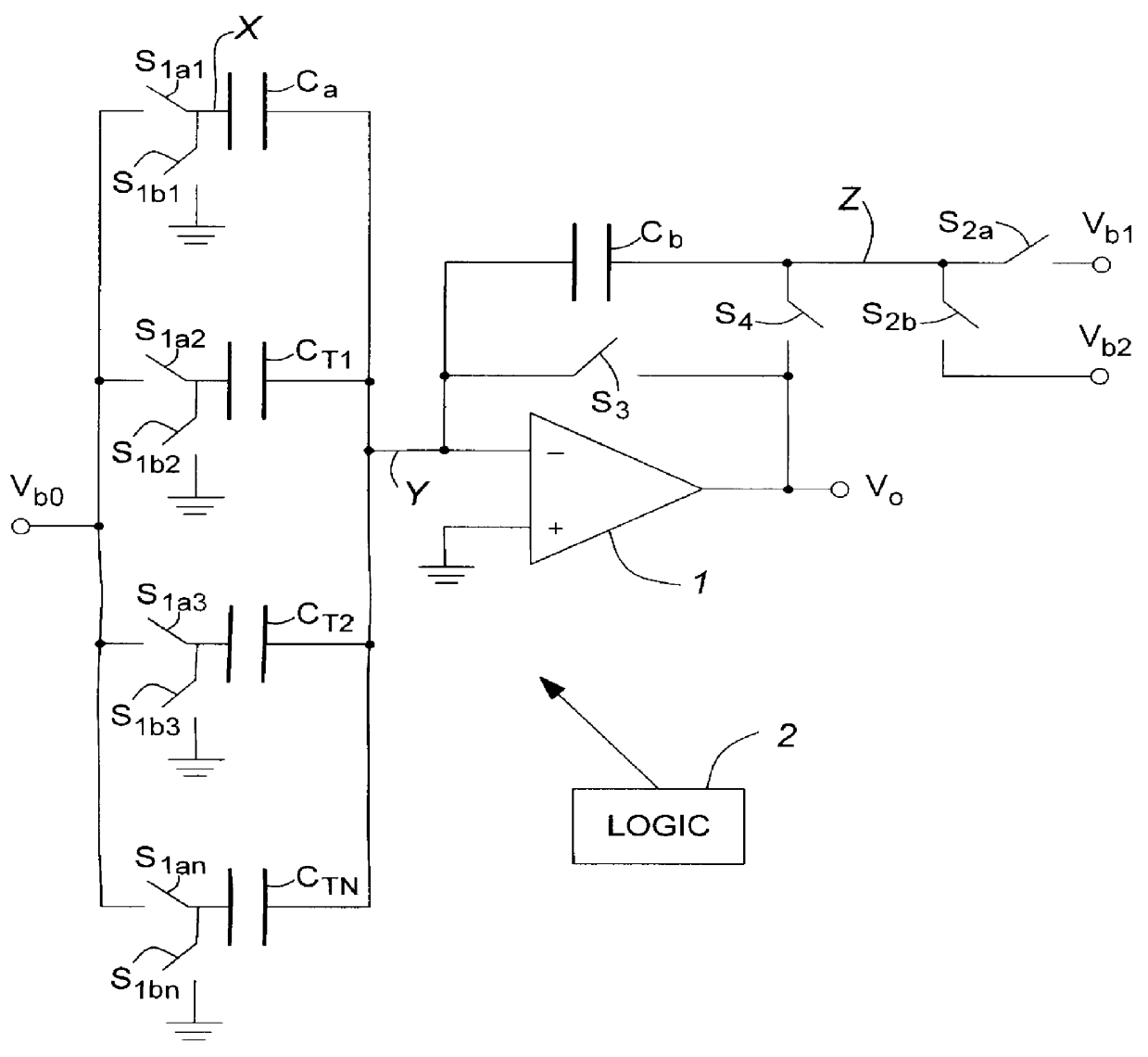
Turning to FIG. 3, the structure is similar to that of FIG. 2, except that switch S.sub.2a replaces switch S.sub.5b and is connected to a voltage reference (node) V.sub.b1, and switch S.sub.2b replaces switch S.sub.5a and is connected to a voltage reference (node) V.sub.b2. The input voltage, instead of voltage V.sub.i =V.sub.r, is V.sub.b0.

Instead of utilizing a plurality of capacitors C.sub.a1 -C.sub.aN each in parallel with groups of trim capacitors C.sub.T, a single capacitor C.sub.a is used, connected to switches S.sub.1a1 and S.sub.1b1 in place of switches S.sub.1a and S.sub.1b. Instead of a group of trim capacitors C.sub.T being connected in parallel with the capacitor to be trimmed, each of plural trim capacitors C.sub.T1 -C.sub.TN is connected between the input to the operational amplifier 1 and a corresponding switch S.sub.1a2 -S.sub.1aN respectively to the input reference voltage node V.sub.b0. Switches S.sub.1b2 -S.sub.1Bn connect the respective junctions between the tri...


PUM


Abstract

Within the field of integrated circuits used in amplifiers, a structure and improved method for calibrating a switched capacitor gain stage wherein the time required to self-calibrate a switched capacitor gain stage and the associated structure are reduced. The invention utilizes only a single calibration step which is performed while the output of the amplifier being calibrated is monitored. Instead of utilizing a plurality of capacitors Ca1-Can each in parallel with groups of trim capacitors CT, a single capacitor Ca is used and connected to switches S1a1 and S1b1. Further, instead of a group of trim capacitors CT being connected in parallel with the capacitor to be trimmed, each of plurality of trim capacitors CT1-CTN is connected between the input to the operational amplifier and a respective corresponding switch S1a2-S1aN to the input reference voltage node Vb0. As well, switches S1b2-S1bn connect the respective junctions between the trim capacitors CT1-CTN to ground.

Description

This invention relates to the field of integrated circuits, and in particular to a structure and improved method for calibrating a switched capacitor gain stage.BACKGROUND TO THE INVENTIONAmplifiers with precise integer gains are required in many analog-to-digital converters and digital-to-analog converters. While relatively precise gains can be obtained with switched-capacitor gain stages, their accuracy is limited to about 1 part in 1000 due to mismatches in the capacitor ratios. Therefore, to achieve higher accuracy, the capacitor ratio must be trimmed. This is referred to herein as calibrating a switched capacitor gain stage.As shown in FIG. 1, a capacitor C typically is trimmed by adding an array of smaller trim capacitors C.sub.T1 -C.sub.TN in parallel with the capacitor C to be trimmed (which trim capacitors are shown also as a variable capacitor). The trim capacitors are connected in parallel with the capacitor C by switches S.sub.1 -S.sub.N. The switches can be implemented ...

Claims


Application Information

Patent Timeline
Patent Type & Authority Patents(United States)
IPC IPC(8): H03F3/00
CPCH03F3/005
Inventor NAIRN, DAVID GRAHAM
Owner PMC-SIERRA
Learn More