Touch fastener strap and splint having buckle retention means

a technology of fastener strap and buckle, which is applied in the field of straps, can solve the problems of individual difficulty in properly applying a splint, difficulty in threading the end of the strap, and special difficulty, and achieve the effects of convenient removal, adjustment, and convenient placement on the wris

Inactive Publication Date: 2000-01-11
MEDICAL SPECIALTIES
View PDF12 Cites 27 Cited by
  • Summary
  • Abstract
  • Description
  • Claims
  • Application Information

AI Technical Summary

Benefits of technology

It is another object of the invention to provide a strap with means for retaining the strap in a buckle which is easy to fabricate.
To remove the splint, straps 32 and 34 and strap member 38 are detached, loosening the splint 30 so the hand can be withdrawn. Retention member 44 functions to prevent the strap member 38 from being withdrawn entirely from the buckle 45. Thus, when the wearer is ready to replace the splint 30, the hand is re-inserted into the splint 30 and the straps 32 and 34 re-attached. Since the strap member 38 has been retained in the buckle 45, it is not necessary to rethread the strap member 38 into the buckle 45 with one hand, or obtain help from someone else. Rather, it is a simple matter to grasp the end of the strap member 38 and pull it back into the proper position for reattachment to the loops 40 on the strap member 38.

Problems solved by technology

It has been observed that some individuals have difficulty properly applying such a splint, since it may be difficult to thread the end of the strap through the relatively narrow buckle with only one hand-the hand not in the splint.
This is particularly difficult if, as is often the case, the patient has injured the dominant hand and must use the other hand.

Method used


Image

  • Touch fastener strap and splint having buckle retention means
  • Touch fastener strap and splint having buckle retention means
  • Touch fastener strap and splint having buckle retention means

Examples


Embodiment Construction

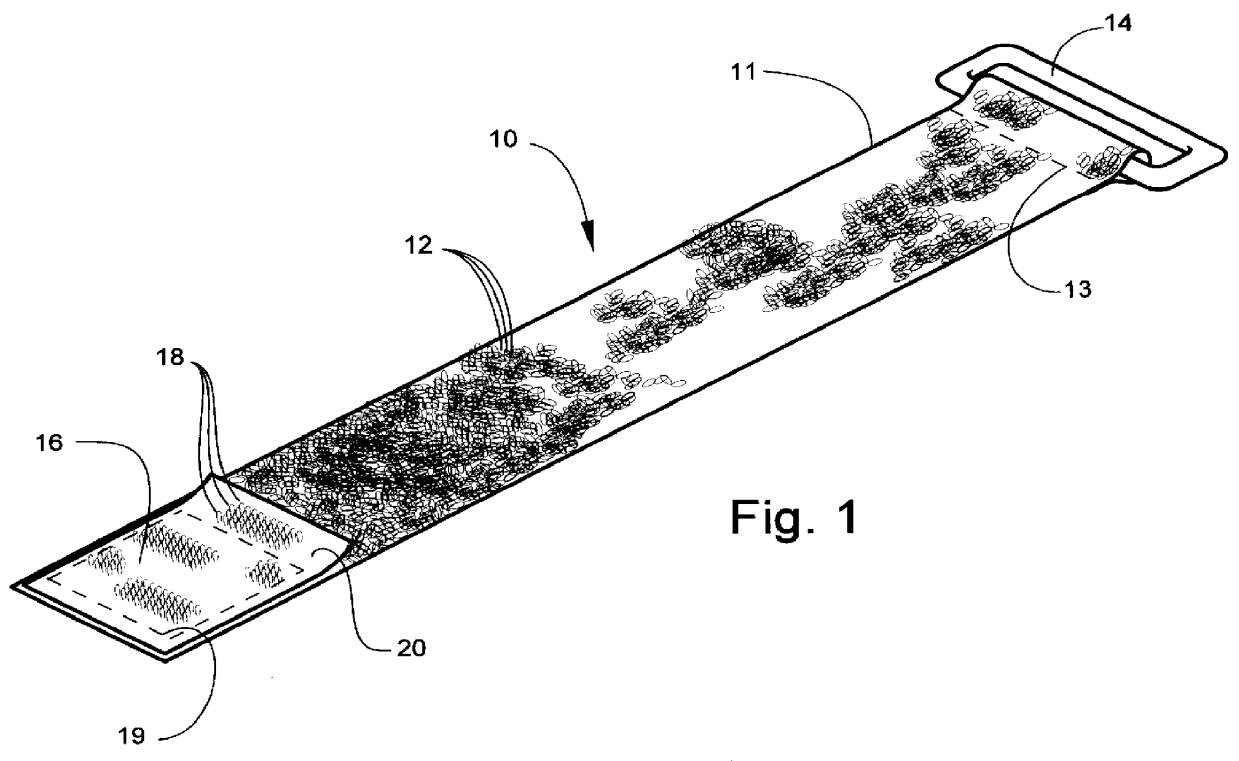
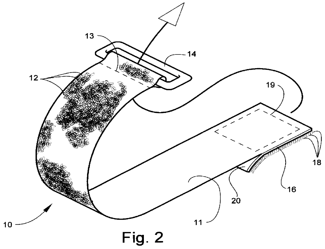
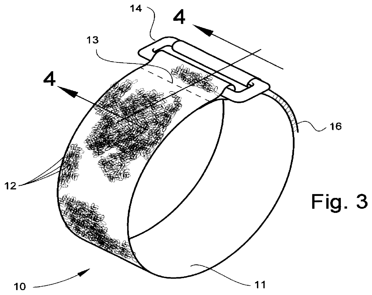
Referring now specifically to the drawings, a strap according to the present invention is illustrated in FIG. 1 and shown generally at reference numeral 10. The strap 10 is formed of an elongate strap member 11 of suitable length for the intended use. Strap member 11 is typically a woven or knitted tape with a loose, unbroken fibrous surface on one side formed of a multitude of loose loops 12. The loops 12 form one-half of a touch fastener system.

A buckle 14 is secured to one end of the strap member 11 by passing one end of the strap member 11 through the buckle 14 and doubling the strap member 11 over on itself. The doubled portion of the strap member 11 is then stitched or with sewing stitches 13 or otherwise joined, such as by ultrasonic welding, to secure the buckle 14 to the end of the strap member 11.

A woven or knitted patch 16 having a multitude of hooks 18 is stitched or ultrasonically welded onto the end area of strap member 11 opposite the buckle 14. Note that the patch 16...


PUM


Abstract

A touch fastener strap of the type which includes an elongate strap member with a buckle on a first end and complementary touch fastener elements carried by the strap member adjacent to an opposing second end. The second end of the strap member may be passed through the buckle, doubled over itself and secured in a desired position by connection of the complementary touch fasteners with each other. The improvement is a retention member carried adjacent the second end of the strap member and being deformable between a relatively thin insertion position wherein the second end of the strap member including the retention means is sufficiently thin to be inserted into and through the buckle in a first direction to form a loop, and a relatively thick retention position wherein the strap member including the retention means is sufficiently thick that it is normally retained in the buckle. The strap is also disclosed with specific reference to a wrist splint.

Description

TECHNICAL FIELD AND BACKGROUND OF THE INVENTIONThis invention relates to a strap having means for retaining the strap in a buckle, and a splint, such as a wrist splint, wherein the strap is retained in the buckle during placement and removal of the splint. The strap facilitates placement of the splint on the body part with only one hand.Numerous types of splints are known in the art of the type which can be removed and replaced by the patient. This is often necessary for bathing, dressing and adjustment of the splint. Many of these types of splints are held in place by straps which extend around the circumference of the splint and are adjusted to hold the splint in position in the correct therapeutic position and at the correct degree of tightness. These straps most often include touch fastener elements for securing the straps in the proper position. By "touch fasteners" is meant conventional hook-and-loop fasteners, or other types of fasteners which operate by means of complementar...

Claims


Application Information

Patent Timeline
Patent Type & Authority Patents(United States)
IPC IPC(8): A61F13/10A61F13/04
CPCA61F13/04A61F13/108
Inventor GAYLORD, ROBERT SCOTT
Owner MEDICAL SPECIALTIES
Why Eureka
Try Eureka