Stepper motor control that adjusts to motor loading

a technology of stepper motor and motor load, applied in the direction of electric programme control, dynamo-electric converter control, instruments, etc., can solve the problems of insufficient resolution, high ripple torque, and several undesirable characteristics of typical stepper motors

Inactive Publication Date: 2000-01-11
NASA
View PDF1 Cites 37 Cited by
  • Summary
  • Abstract
  • Description
  • Claims
  • Application Information

AI Technical Summary

Problems solved by technology

However, typical stepper motors exhibit several undesirable characteristics.
Principal among these characteristics are: insufficient resolution due to a relatively low number of steps per revolution (e.g., 200 steps per motor revolution); a high ripple torque; and a high constant internal power dissipation regardless of motor load.
While the resolution and ripple torque problems can be addressed by providing high resolution motor command signals, the problem of constant internal power dissipation has been a continuing source of power loss.
The unnecessary production and build-up of heat can be detrimental to the motor itself as well as surrounding components.

Method used


Image

  • Stepper motor control that adjusts to motor loading
  • Stepper motor control that adjusts to motor loading
  • Stepper motor control that adjusts to motor loading

Examples


Embodiment Construction

)

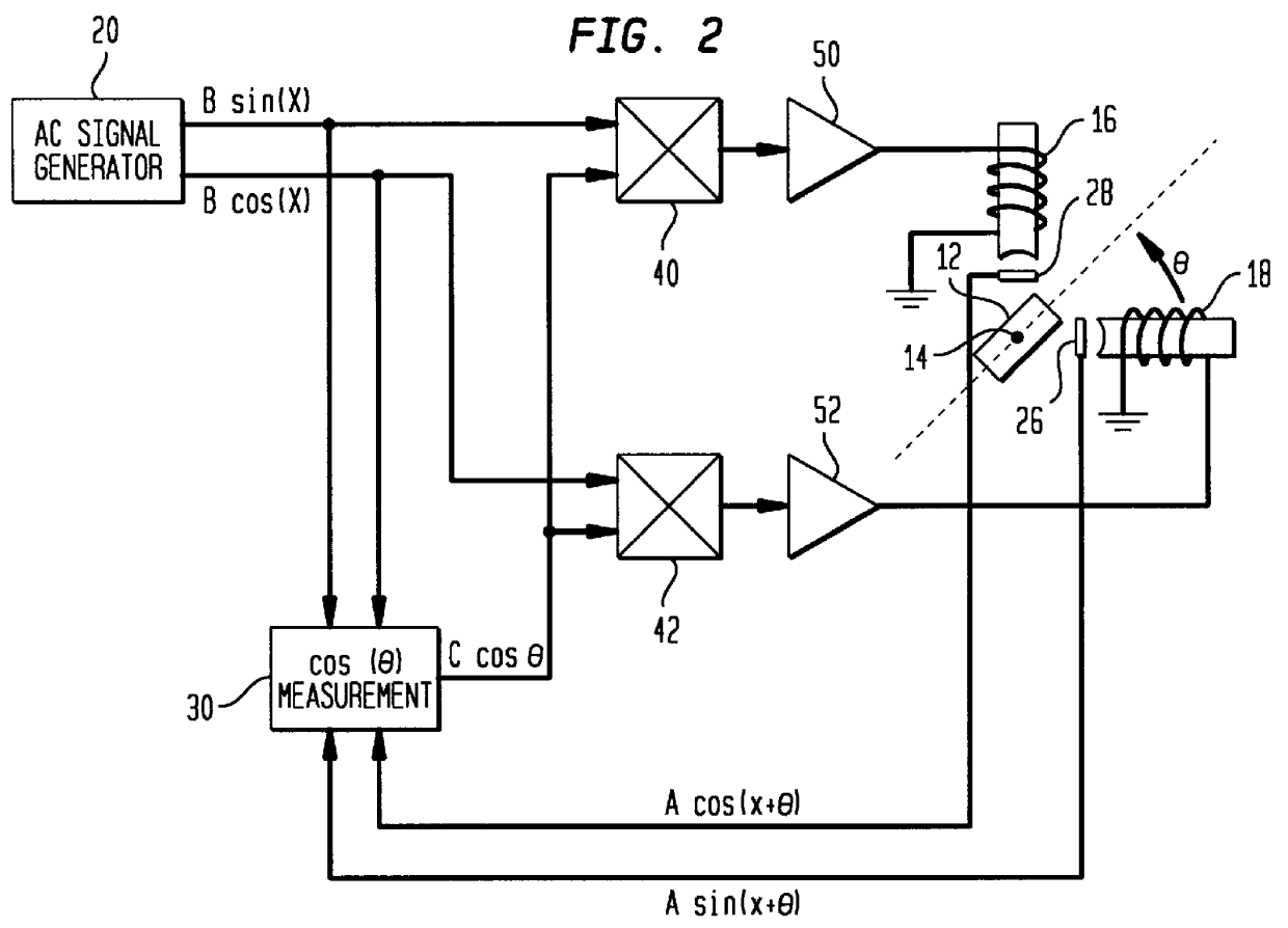
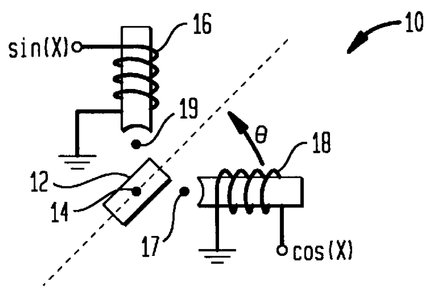
Referring now to the drawings, and more particularly to FIG. 1, a conventional stepper motor is shown schematically and referenced generally by 10. By way of example, the stepper motor shown is a two-phase stepper motor having a rotor 12 that is typically a permanent magnet mounted such that it can rotate about an axis 14 thereof. Two-phase stepper motor 10 also has a multi-phase stator that defines, in this example, two phases of the stepper motor. The two phases of the multi-phase stator are illustrated schematically by windings 16 and 18.

As is known in the art, a sine wave of current is applied to one phase (e.g., a signal of the form sin(X) applied to winding 16) and a cosine wave of current is applied to the second phase (e.g., a signal of the form cos(X) applied to winding 18). The amplitude of the sine and cosine terms defines the amplitude of the applied current and the frequency of the sine and cosine terms defines the rate at which rotor 12 turns. The torque produced by r...


PUM


Abstract

A system and method are provided for controlling a stepper motor having a rotor and a multi-phase stator. Sinusoidal command signals define a commanded position of the motor's rotor. An actual position of the rotor is sensed as a function of an electrical angle between the actual position and the commanded position. The actual position is defined by sinusoidal position signals. An adjustment signal is generated using the sinusoidal command signals and sinusoidal position signals. The adjustment signal is defined as a function of the cosine of the electrical angle. The adjustment signal is multiplied by each sinusoidal command signal to generate a corresponding set of excitation signals, each of which is applied to a corresponding phase of the multi-phase stator.

Description

ORIGIN OF THE INVENTIONThe invention was made by employees of the United States Government and may be manufactured and used by or for the Government for governmental purposes without the payment of any royalties.1. Field of the InventionThis invention relates to control systems for stepper motors. More specifically, the invention is a control system and method for stepper motors that adjusts to motor loading in order to reduce internal power dissipation losses.2. Description of the Related ArtStepper motors are used in a wide variety of machines to provide digital control of moving parts. However, typical stepper motors exhibit several undesirable characteristics. Principal among these characteristics are: insufficient resolution due to a relatively low number of steps per revolution (e.g., 200 steps per motor revolution); a high ripple torque; and a high constant internal power dissipation regardless of motor load. While the resolution and ripple torque problems can be addressed by...

Claims


Application Information

Patent Timeline
Patent Type & Authority Patents(United States)
IPC IPC(8): H02P8/36H02P8/00
CPCH02P8/00H02P8/36
Inventor HOWARD; DAVID E.NOLA; FRANK J.
Owner NASA
Why Eureka
Try Eureka