Arrangement for orienting a fuel injector to a fuel manifold cup

a technology for orienting a fuel injector and a manifold, which is applied in the direction of liquid fuel feeders, machines/engines, couplings, etc., can solve the problems of engine causing undesired stress, distortion and/or movement, and fuel manifold causing some kind of distortion

Inactive Publication Date: 2000-02-01
FORD GLOBAL TECH LLC
View PDF16 Cites 51 Cited by
  • Summary
  • Abstract
  • Description
  • Claims
  • Application Information

AI Technical Summary

Problems solved by technology

Improperly targeted fuel injectors may derogate engine performance and / or compliance with applicable vehicle standards.
Once the fuel injector nozzles have seated in properly targeted positions in the socket receptacles, a need for further tightening of such fasteners in order to secure the fuel manifold on the engine may induce undesired stress, distortion and / or movement.
For example, if fuel injector nozzles have been seated in properly targeted positions in respective socket receptacles in engine intake manifold runners before the manifold attachment fasteners have been fully torqued, the fuel manifold may distort in some way, and / or there may be some relative movement between some component parts, as the fasteners are finally tightened to full installation torque.
With prevailing manufacturing procedures and dimensional tolerances of manufactured parts, it seems that the possibility of such distortion, or movement of component parts, at time of fuel manifold assembly to an engine, cannot be totally foreclosed in all circumstances.
In certain circumstances, the presence of strict axial constraint may be undesirable from the standpoint of assembling a fuel manifold to an engine.
For example, it is believed that strict axial constraint may contribute to undesired stress, distortion, and / or component part movement occurring during manifold assembly to an engine.

Method used


Image

  • Arrangement for orienting a fuel injector to a fuel manifold cup
  • Arrangement for orienting a fuel injector to a fuel manifold cup
  • Arrangement for orienting a fuel injector to a fuel manifold cup

Examples


Embodiment Construction

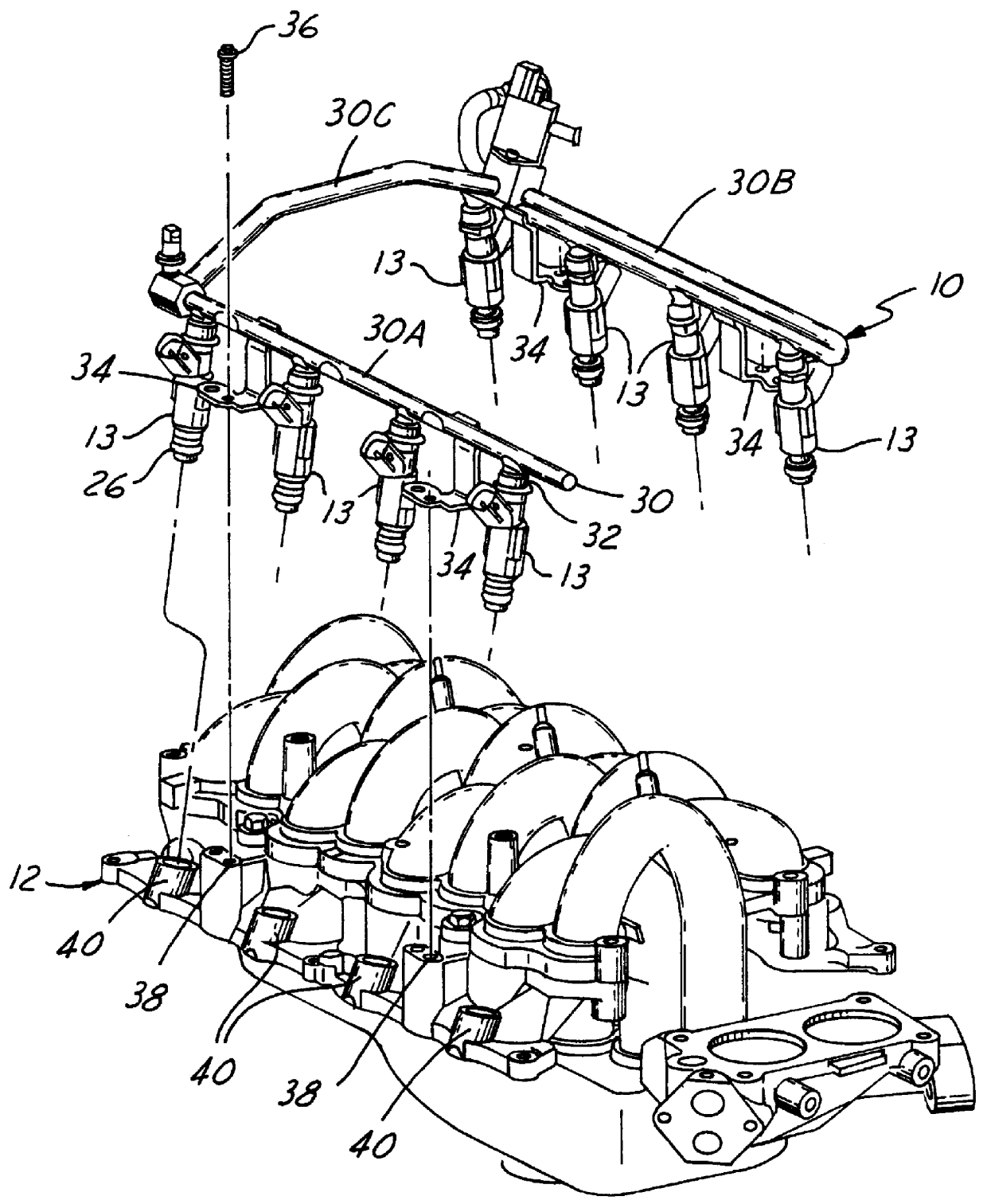
FIG. 1 shows a representative fuel manifold 10 embodying principles of the present invention, and adapted for attachment to an intake manifold 12 of a spark-ignited, internal combustion engine. The illustrated manifolds 10, 12 are configured for an eight-cylinder V-type engine, with fuel manifold 12 comprising eight electric-operated fuel injectors 13 of the top-feed type.

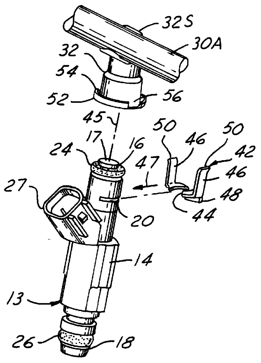
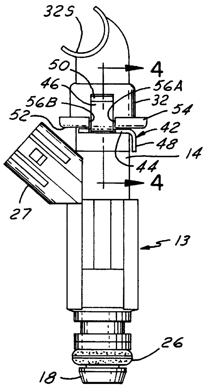
As can be more fully seen in FIGS. 2-4, each fuel injector 13 comprises a body 14, including a fuel inlet tube 16 at one axial end. The free end of fuel inlet tube 16 provides a fuel inlet opening 17 via which pressurized liquid fuel can enter the fuel injector. The opposite axial end of fuel injector 13 comprises a nozzle 18 containing one or more metering orifices from which fuel is injected out of fuel injector body 14.

The exterior of a portion of body 14 surrounding fuel inlet tube 16 comprises radially outwardly open grooves 20 diametrically opposite each other. An O-ring seal 24 is disposed about tube 16 just...


PUM


Abstract

An orientation clip (42) has an axially- and circumferentially-united attachment with a fuel injector (13) to orient the fuel injector circumferentially within a cup (32) on a fuel manifold (30). The clip has axially extending orientation tabs (46) that pass through open spaces provided by notches (56) in the rim of the cup to circumferentially locate the clip to the cup, and hence the fuel injector to the cup.

Description

1. Field of the InventionThis invention relates generally to an arrangement for orienting an electric-operated fuel injector to an injector-receiving cup of a fuel manifold. The disclosed embodiment of the invention illustrates an arrangement for orienting a top-feed fuel injector to a cup of a fuel manifold using an orientation clip that is attached to the fuel injector and that includes a feature relating with a complementary feature of the cup to circumferentially locate the fuel injector about a center line of the cup and fuel injector while allowing the fuel injector, once circumferentially oriented, to position itself axially within the cup when being assembled to the fuel manifold.2. Background InformationSpark-ignited, fuel-injected internal combustion engines enjoy extensive usage as the powerplants of automotive vehicles. Fuel is injected into an intake system of such an engine by electric-operated fuel injectors of a fuel manifold assembled to the engine. Such a manifold ...

Claims


Application Information

Patent Timeline
Patent Type & Authority Patents(United States)
IPC IPC(8): F02M55/00F02M61/14F02M61/00F02M69/46
CPCF02M61/145F02M69/465F02M2200/16F02M2200/856F02M2200/852F02M2200/853
Inventor TAYLOR, TIMOTHY GERALDCOLE, MATTHEW MOYLERROBERTS, JAMES BRADENFORT, WILLIAM BEAL
Owner FORD GLOBAL TECH LLC
Why Eureka
Try Eureka