Optical control type phased array antenna apparatus equipped with optical signal processor

a phased array antenna and optical signal processor technology, applied in the direction of antenna arrays, electrical devices, antennas, etc., can solve the problems of large optical processing system size, inability to receive plurality of signals, and inability to radiate radio signals

Inactive Publication Date: 2000-02-01
ATR ADAPTIVE COMMUNICATIONS RES LAB
View PDF11 Cites 35 Cited by
  • Summary
  • Abstract
  • Description
  • Claims
  • Application Information

AI Technical Summary

Problems solved by technology

However, the optical control type phased array antenna apparatus of the first prior art shown in FIG. 16 has had such a problem that the incoming radio wave signal cannot be received and such a problem that a plurality of radio signals cannot be radiated.
Furthermore, the second prior art disclosed in the above-mentioned prior art document has had suc

Method used


Image

  • Optical control type phased array antenna apparatus equipped with optical signal processor
  • Optical control type phased array antenna apparatus equipped with optical signal processor
  • Optical control type phased array antenna apparatus equipped with optical signal processor

Examples


second preferred embodiment

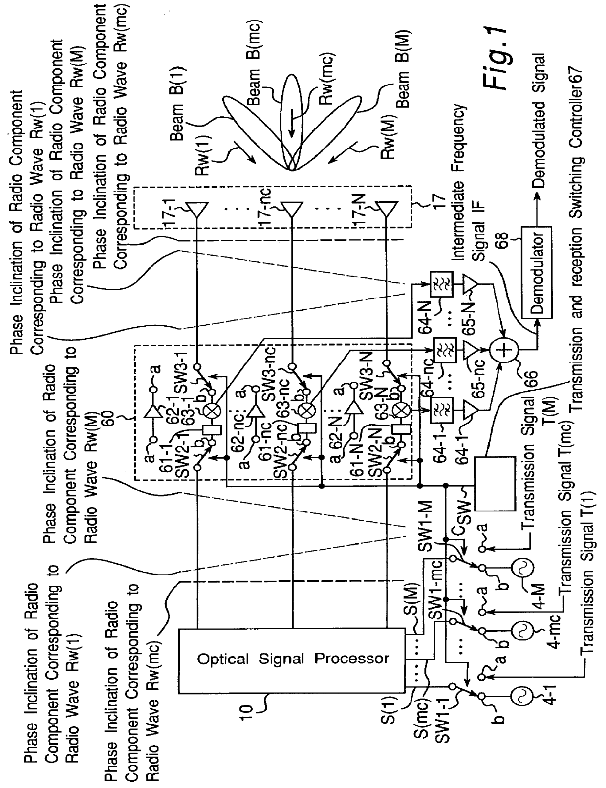
FIG. 8 is a block diagram showing a configuration of an optical control type phased array antenna apparatus according to a second preferred embodiment of the present invention. The optical control type phased array antenna apparatus of the second preferred embodiment is characterized in that a transceiver module 70 is used in place of the transceiver module 60 in the optical control type phased array antenna apparatus of the first preferred embodiment shown in FIG. 1, and it can be applied to a case where the frequency of the radio wave signal Rw(m) and the frequency of the transmitting signal T(m) to be transmitted in correspondence with the radio wave signal differ from each other.

That is, as shown in FIG. 8, the transceiver module 70 of the second preferred embodiment is constructed of a combination of circuits comprising a phase inverter 61-n, a power amplifier 62-n, a mixer 63-n, band-pass filters 71-n and 72-n and a circulator 73-n for each antenna element 17-n. In this case, ...

first modified preferred embodiment

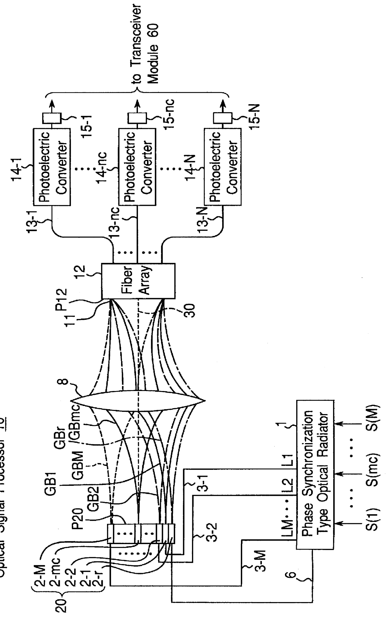
FIG. 9 is a block diagram showing a configuration of an optical signal processor 10a of an optical control type phased array antenna apparatus according to a first modified preferred embodiment of the present invention.

The optical signal processor 10a is characterized in that the optical signal processor 10 shown in FIG. 2 is further provided with a movement mechanism 57 for moving the radiation lens array 20 one-dimensionally in a direction perpendicular to the optical axis 30 and a controller 58 for controlling the operation of the movement mechanism 57.

In the optical control type phased array antenna apparatus of the first modified preferred embodiment, control of the direction in which a receivable radio wave signal comes and the radiating direction of the radiation pattern are executed as follows. That is, based on the direction in which the radio wave signal comes and the desired radiating direction, the controller 58 controls the movement mechanism 57 so that the radiation le...


PUM


Abstract

Disclosed is an optical control type phased array antenna apparatus having an array antenna of antenna elements. An optical signal processor optically processes input high-frequency signals, and outputs optically processed signals including signal components having phases corresponding to directions in which radio wave signals come and having frequencies equal to those of the input high-frequency signals. Then, each frequency converter mixes a received signal with the optically processed signal in correspondence with the antenna element, and outputs a frequency-converted signal having a frequency of a difference between a frequency of the received signal and a frequency of the optically processed signal. Further, a combiner combines the frequency-converted signals. When reference signals each having a frequency that differs from the frequency of the corresponding radio wave signal by an intermediate frequency are inputted to the optical signal processor as the input high-frequency signals, intermediate frequency signals having the intermediate frequencies and corresponding to the radio wave signals are outputted as received signals from the combiner.

Description

1. Field of the InventionThe present invention relates to an optical control type phased array antenna apparatus, and in particular, to an optical control type phased array antenna for receiving a plurality of radio wave signals coming in predetermined directions and / or transmitting radio wave signals in predetermined directions, by using an optical signal processor by means of Fourier transform processing a high-frequency signal in an optical space, without executing any digital signal processing.2. Description of the Prior ArtFIG. 16 is a block diagram of an optical control type phased array antenna apparatus of a first prior art disclosed in the Japanese Patent Laid-Open Publication No. 3-044202.Referring to FIG. 16, an optical radiator 101 splits a beam of light radiated from a laser diode provided inside the optical radiator 101, into two branched beams of light. One branched beam of light is directly outputted as a first beam of light 103, while the frequency of another branch...

Claims


Application Information

Patent Timeline
IPC IPC(8): H01Q3/26H01Q3/30H01Q19/00H01Q21/00H01Q25/00
CPCH01Q3/2676
Inventor JI, YUINAGAKI, KEIZOIMAI, NOBUAKIKARASAWA, YOSHIO
Owner ATR ADAPTIVE COMMUNICATIONS RES LAB
Why Eureka
Try Eureka