Permanent magnet rotor type electric motor with different permanent magnet materials

a permanent magnet, rotor-type technology, applied in the direction of dynamo-electric machines, magnetic circuit rotating parts, magnetic circuit shapes/forms/construction, etc., can solve the problems of reducing the size of the rotor core, and limiting the shape of the permanent magn

Inactive Publication Date: 2000-02-15
FUJITSU GENERAL LTD
View PDF11 Cites 105 Cited by
  • Summary
  • Abstract
  • Description
  • Claims
  • Application Information

AI Technical Summary

Problems solved by technology

The ferrite magnet is less expensive and available for forming the permanent magnet in various shapes due to easiness of forming thereof, but the magnetic flux density is low, therefore hindering the reduction in size of the rotor core.
On the other hand, the rare-earth magnet has a high magnetic flux density, so that the reduction in size of the rotor core is easy, but the shape of the permanent magnet is limited by difficulty of forming thereof.
In addition, the rare-earth magnet is more expensive than the ferrite magnet.
Accordingly, the inductance on the axis q is small, so that the difference of the inductance on the axis q and the inductance on the axis d (parameter of a reluctance torque: refer to the aforementioned operational expression) becomes small, with the result that a sufficient reluctance torque cannot be attained.
In the case that the magnetic pole is formed of only the rare-earth magnet, the magnetic flux density is high, so that the magnet does not occupy the most of the rotor core as the ferrite magnet, but the magnetic flux density is often excessively high, and additionally the rare-earth magnet is expensive, therefore the motor is increased in cost.
As described hereinbefore, conventionally, a proper permanent magnet having an intermediate state between the ferrite magnet and the rare-earth magnet is troublesome to obtain, that is to say it is difficult to select the required magnetic flux density and reluctance torque, with low cost.

Method used


Image

  • Permanent magnet rotor type electric motor with different permanent magnet materials
  • Permanent magnet rotor type electric motor with different permanent magnet materials
  • Permanent magnet rotor type electric motor with different permanent magnet materials

Examples


Embodiment Construction

)

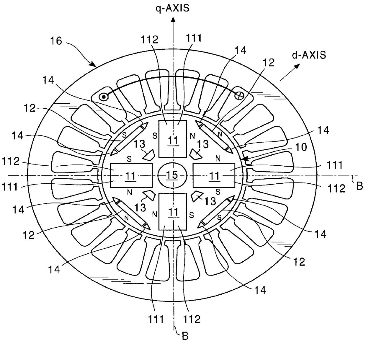
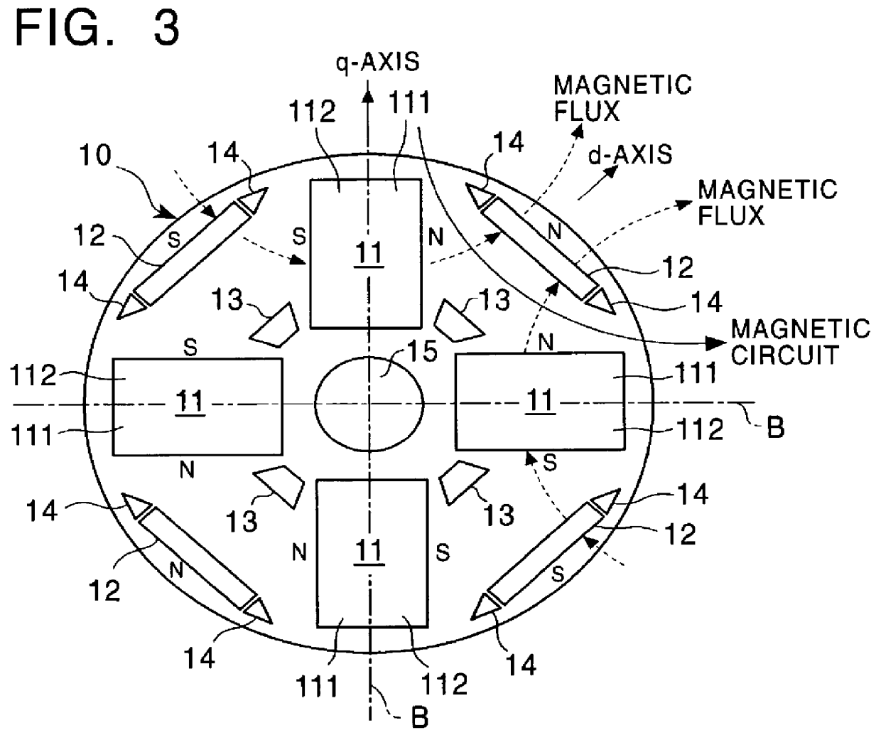
In the present invention, a magnetic flux density and a reluctance torque can be established in required values by forming each magnetic pole in a rotor core of a plurality of permanent magnets and making the permanent magnets of different magnetic materials. Therefore, as shown in FIG. 1 and FIG. 3, each magnetic pole in a rotor core 10 is formed of a first permanent magnet 11 of ferrite magnet and a second permanent magnet 12 of rare-earth magnet, and the permanent magnet 11 is shared between the adjacent magnetic poles in this embodiment.

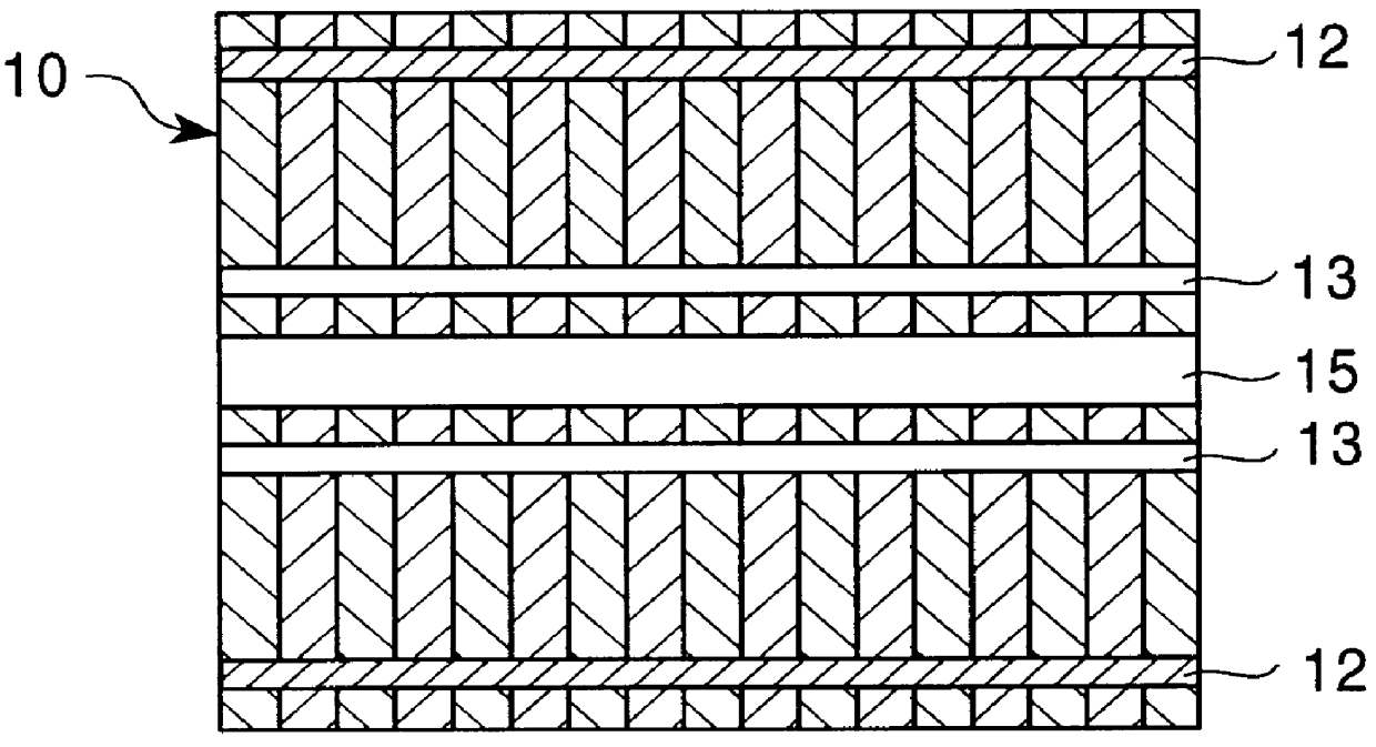
Incidentally, the rotor core 10 is made of a magnetic steel plate and disposed inside a stator core 16 generating a rotation magnetic field. The explanation of the stator core 16 will be omitted since, in the performance of the present invention, the stator core 16 may be similar to the stator core 1 shown in FIG. 8 which is explained hereinbefore.

The first permanent magnet 11 made of the ferrite magnet is formed to be a band plate shape which i...


PUM


Abstract

In an electric motor, such as a DC brushless motor or the like, having a permanent magnet in a rotor, each magnetic pole is formed of three permanent magnets, and the permanent magnets are made of at least two kinds of magnetic materials represented by ferrite magnet and rare-earth magnet. Thus, in a permanent magnet rotor type electric motor, a reluctance torque and a magnetic flux density can be selectively established, and cost is reasonable, corresponding to the quality.

Description

1. Field of the InventionThis invention relates to an electric motor having a permanent magnet in a rotor, such as Brushless DC motor or the like and, more specifically, to an electric motor in which a magnetic flux density, a reluctance torque and so on can be selectively established, appropriate as a driving source of a compressor of an air conditioner, for example.2. Description of the Related ArtIn the electric motor of the type as described above, a permanent magnet is embedded in a core of an inner rotor of the electric motor, an example thereof being shown respectively in FIG. 8 and FIG. 9 each of which is a plane view showing the inside of this electric motor from a plan perpendicular to the axis of rotation.In the example shown in FIG. 8 a rotor core 2 is disposed inside a stator core 1, having 24 slots for example, in which a field magnet rotates. In this case, the number of poles of the electric motor is four, therefore four permanent magnets 3 are arranged in the rotor c...

Claims


Application Information

Patent Timeline
Patent Type & Authority Patents(United States)
IPC IPC(8): H02K1/27H02K15/03H02K21/14
CPCH02K1/2766
Inventor NARITA, KENJISUZUKI, TAKASHIOKUDERA, HIROYUKIKAWAI, YUJISOUMA, YUJIKAWANISHI, KOJIFUKUDA, YOSHICHIKA
Owner FUJITSU GENERAL LTD
Why Eureka
Try Eureka