Optical apparatus comprising an adjustable holder device

an adjustable and optical technology, applied in the direction of electrical devices, lasers, instruments, etc., can solve the problems of relatively complicated adjustment and fixation process, or the prior art of this kind requires either relatively complicated auxiliary fastener means, and achieve excellent sliding characteristics

Inactive Publication Date: 2000-02-15
SICK AG
View PDF14 Cites 30 Cited by
  • Summary
  • Abstract
  • Description
  • Claims
  • Application Information

AI Technical Summary

Benefits of technology

In a solution of this kind the assembling together of the component and the adjustment can take place in a single working process and can be carried out by an automatic unit. Furthermore, the fixation by means of an adhesive, by means of other mechanical fastening means or an additional working step (for example flanging) is avoided, because the press fit ensures a reliable fixation.
The use, in accordance with of the invention, of zinc is particularly advantageous, with the components or the holders preferably being manufactured in the pressure die casting process. In addition to particular stability, zinc on zinc has excellent sliding characteristics. By way of example, a press-fitted seating is still ensured even after five to six subsequent displacements of the connection elements relative to one another.

Problems solved by technology

In just the same way it is known to fix the adjusted focal position by means of a screw connection which requires additional fastening means in disadvantageous manner.
Prior art of this kind requires either relatively complicated auxiliary fastener means and / or relatively complicated working processes for the adjustment and fixation.

Method used


Image

  • Optical apparatus comprising an adjustable holder device
  • Optical apparatus comprising an adjustable holder device
  • Optical apparatus comprising an adjustable holder device

Examples


Embodiment Construction

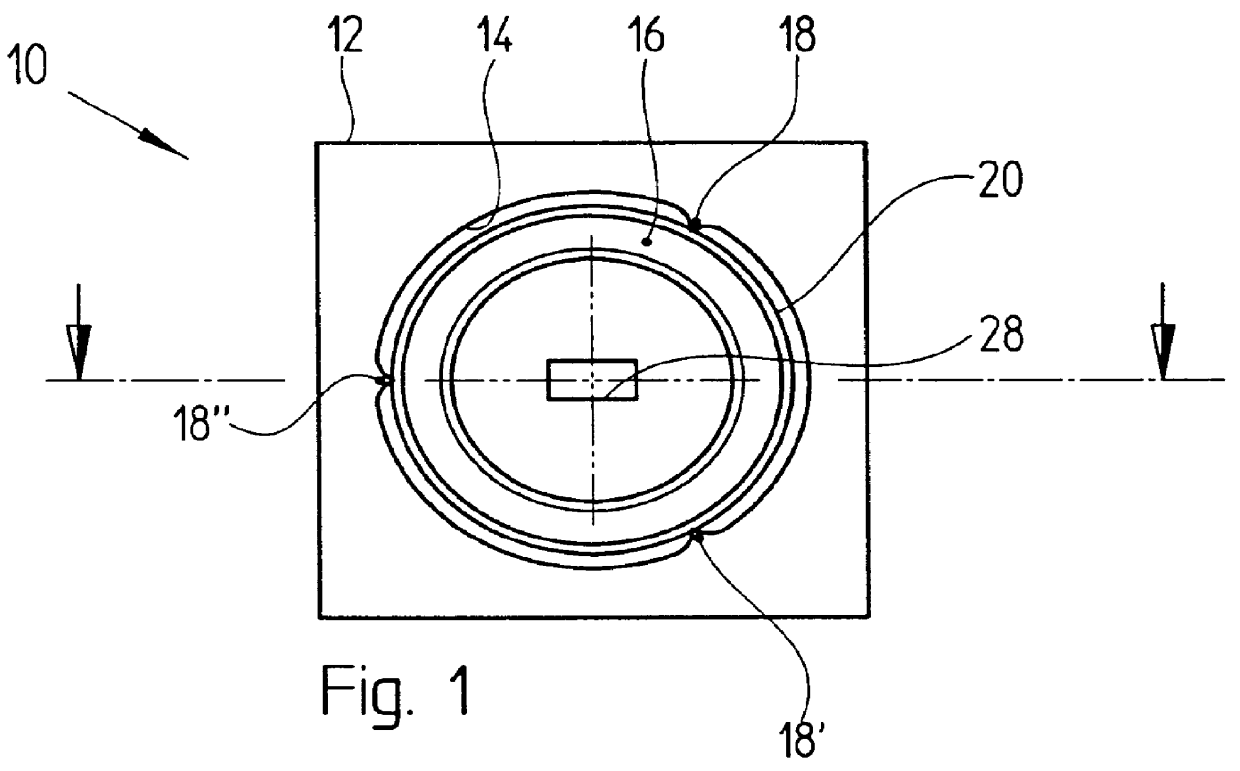
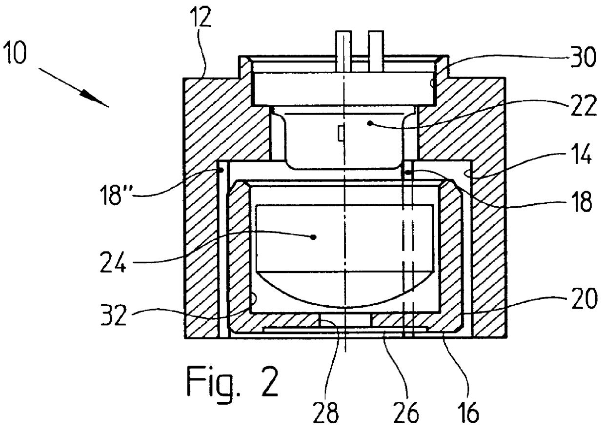
The laser diode module 10 shown in FIG. 1 has a first outer housing part 12 with a cylindrical opening 14, into which a second cup-shaped inner housing part 16 is adjustably inserted relative to the first housing part 12. The second housing part 16 is held by three runners or splines 18, 18', 18" arranged on the first housing part 12, which extend in the axial direction of the cylindrical opening 14 and are uniformly distributed peripherally within the opening 14. The runners 18, 18', 18" press with a press fit (interference fit) against the jacket surface 20 of the cup-like second housing part 16, so that the latter can be axially shifted for the adjustment after overcoming the holding force of the press fit. The two housing parts 12, 16 preferably consist of pressure die cast zinc, since zinc on zinc has, on the one hand, good sliding characteristics and, on the other hand, however, also a stable sticking capability.

It can be seen from FIG. 2 that a laser diode 22 is fixed in the ...


PUM


Abstract

A laser diode module as an example has a laser diode pressed into a first housing part and a lens of an optical collimation system pressed into a cup-shaped second housing part. The second housing part is pressed into a cylindrical opening of the first housing part. In the opening there are molded three runners, which extend in the axial direction and are uniformly distributed in the peripheral direction, with the runners engaging on the jacket surface of the second housing part. The runners and the jacket surface form connection elements which are press-fitted together and which enable, apart from the connection, an adjustment of the lens relative to the laser diode. Pressure die cast zinc is in particular suitable as the material for the connection elements. An adhesive bond is not required with a holder of this kind.

Description

The invention relates to an optical apparatus with an adjustable holder device having at least one first component which can be aligned with a second component, of which both components have optical elements, or the first component is an optical element and the second component is a holder therefor.DESCRIPTION OF PRIOR ARTAn apparatus of this kind has components which can be aligned relative to one another, for example a laser diode and an associated optical collimation system, with each of these optical elements being anchored in a holder. In this respect it is known either to align the optical elements relative to one another in their holders or to align the holders relative to one another by auxiliary fastening means and subsequently to fix the adjusted focal position by means of an adhesive. In just the same way it is known to fix the adjusted focal position by means of a screw connection which requires additional fastening means in disadvantageous manner.Prior art of this kind ...

Claims


Application Information

Patent Timeline
Patent Type & Authority Patents(United States)
IPC IPC(8): G02B7/00G02B6/42G02B7/02H01S5/00H01S5/022
CPCG02B6/4204G02B6/4226G02B7/00G02B7/02
Inventor HIPPENMEYER, HEINRICHANSELMENT, CHRISTOPH
Owner SICK AG
Why Eureka
Try Eureka