Plug core heat exchanger

a heat exchanger and core technology, applied in indirect heat exchangers, lighting and heating apparatus, ways, etc., can solve the problems of incomplete combustion products and lowered reaction temperature, and achieve the effect of maximizing both the flow length and the residence time of combustion gases

Inactive Publication Date: 2000-02-22
BARKAN KENNETH C
View PDF2 Cites 12 Cited by
  • Summary
  • Abstract
  • Description
  • Claims
  • Application Information

AI Technical Summary

Benefits of technology

An object of the present invention is to provide an apparatus for transferring heat to a fluid from combustion gases which creates a helical flow path for the combustion gases which maximizes both the flow length and residence time of the combustion gases within the apparatus.

Problems solved by technology

These high concentrations of undesirable components result from a lowered reaction temperature caused by the cold fluid entering the heat exchanger adjacent the burner.
Cold fluid draws heat from the reacting gases resulting in the incomplete products of combustion.

Method used


Image

  • Plug core heat exchanger
  • Plug core heat exchanger
  • Plug core heat exchanger

Examples


Embodiment Construction

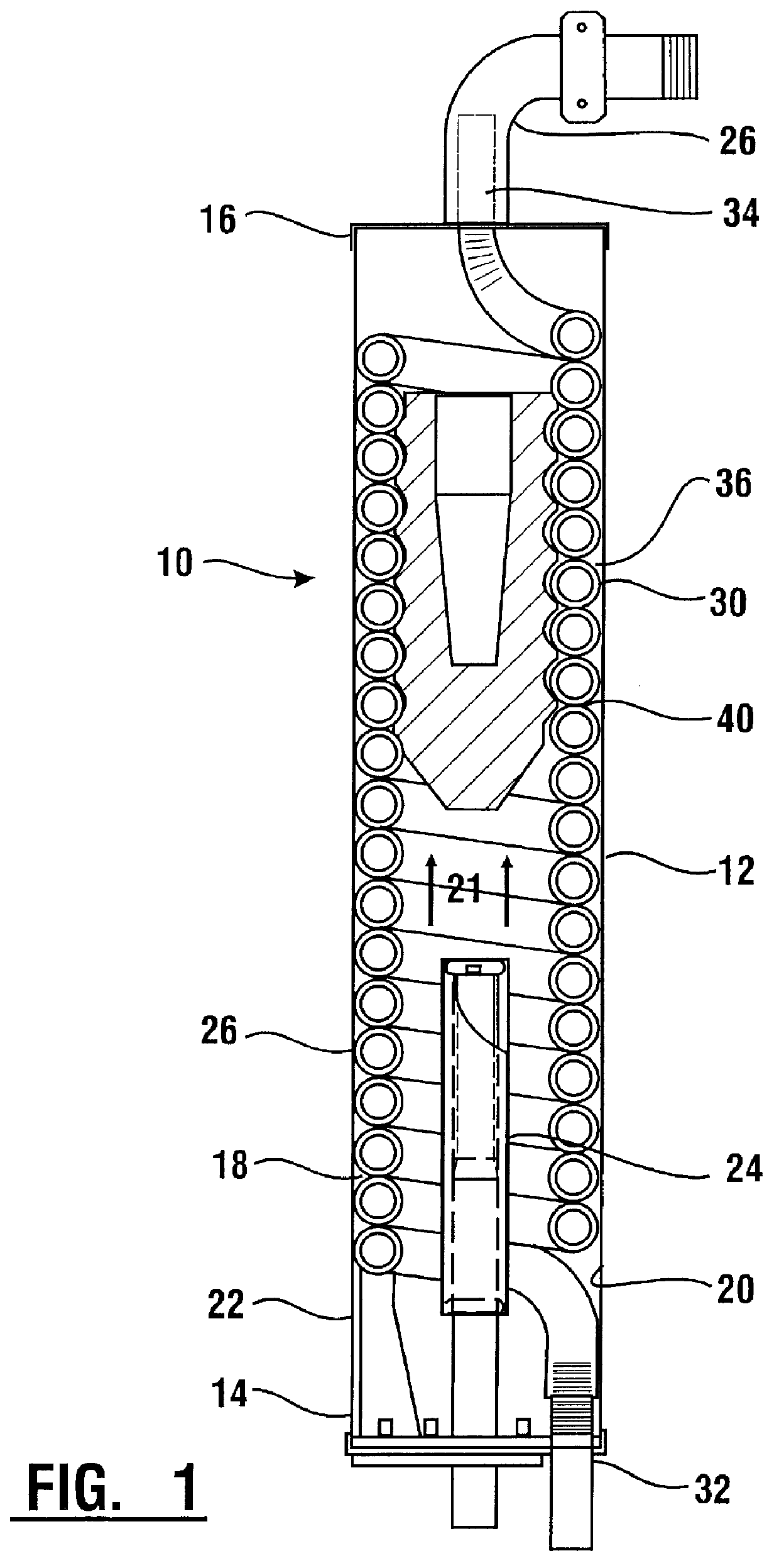
Referring now to the drawings and particularly to FIG. 1, a first embodiment of the plug core heat exchanger 10 of the present invention is shown. The plug core heater exchanger 10 comprises a cylindrical housing 12 which extends from a first end 14 to a second end 16. Both a combustible gas and a fluid to be heated enter an interior portion 18 of the housing at the first end 14 and co-currently flow through the interior portion until they exit the housing at the second end 16.

The interior portion 18 is bounded by the inner surface 20 of the housing. The housing is manufactured from stainless steel which provides a corrosion resistant and thermal resistant material for long heat exchanger life. An external surface 22 of the housing is insulated to decrease heat transfer from the interior portion through the housing to the external surface.

The combustible gas flows from a combustible gas source through a conduit which transports the gas through the first end 14 to a burner 24. Air is...


PUM


Abstract

An apparatus (10) for transferring heat to a fluid from combustion gases including a housing (12) extending between a first end (14) and a second end (16). The apparatus further includes a burner (24) in which a combustible gas and oxygen react to form hot combustion gases which flow from the burner to a gas outlet (28) in the second end. The fluid flows in a length of helically coiled tubing (30) extending the length of the housing. The tubing includes a fin portion (36) which is spirally wound about the length of tubing. The apparatus further includes a core member (40) which extends within the coils of the tubing, and which engages the tubing. The core member includes a spirally-wound threaded area (62) about which the tubing is wrapped. The core member further includes a recessed portion (66) which creates stagnant air pocket adjacent the end of the core member. In operation the combustion gases leaving the burner are prevented from being short circuited and are directed into the tubing by the core member. The combustion gases are routed by the fin portion along a helical flow path throughout the length of the core member. The combustion gases are transferred into contact with the core member every revolution around the tubing. The recessed portion reduces the heat transfer between the core member and the exiting combustive gases.

Description

This invention relates to heat exchangers, particularly to heat exchangers which include plug core flow restrictors.Heat exchangers with cylindrical shells and helical tubes for heating fluids in the tubes are well known in the prior art. Typically the fluid flowing in the tubes is heated with a co-current flowing combustion gas provided by a burner located within the shell. These heat exchangers are typically high efficiency burners which are adapted for use in domestic applications. The exchangers are used continuously, and minor modifications which result in increased heat transfer efficiencies provide great cost savings.There are two major ways to increase the efficiency of a heat transfer apparatus of the present type. The first way is to increase the conductive, convective and radiative heat transfer from the combustion gases to the water flowing through the tubes. This can be done by increasing the transfer time for heat transfer between the gases and the helical coils by div...

Claims


Application Information

Patent Timeline
Patent Type & Authority Patents(United States)
IPC IPC(8): F24H1/43F24H1/22F28D7/02
CPCF24H1/43F28D7/024
Inventor BARKAN, KENNETH C.
Owner BARKAN KENNETH C
Why Eureka
Try Eureka