Integral tubing head and rotator

Inactive Publication Date: 2000-02-22
ROBBINS & MYERS ENERGY SYST
View PDF28 Cites 34 Cited by
  • Summary
  • Abstract
  • Description
  • Claims
  • Application Information

AI Technical Summary

Benefits of technology

Further, in the preferred embodiment, the drive gear and the driven gear engage each other between the minimum diameter and the maximum diameter of the internal bore. The drive gear and the driven gear may be comprised of any compatible gears suitable for performing their functions or purpose and which engage each other between the minimum and maximum diameters of the internal bore. However, preferably, the drive gear is comprised of a worm and the driven gear is comprised of a worm gear. Further, in the preferred embodiment, the worm and the worm gear are non-enveloping in order to facilitate the removal of the tubing hanger from the internal bore without first disengaging the worm from the worm gear.
The worm gear is comprised of a plurality of worm gear teeth and the worm is comprised of a plurality of worm teeth. These worm gear and worm

Problems solved by technology

As a result, the tubing rotator may prolong the life of the tubing string.
Further, the constant movement of the tubing string relative to the rod string may inhibit or reduce buildup of wax and other materials within the tubing string.
Conventional tubing heads are not typically able to be retrofitted to accommodate the necessary structure of a tubing rotator, including the drive system for causing the rotation of the tubing string.
This arrangement may increase the overall height of the wellhead and may result in the instability of the wellhead by weakening its overall structure.
However, any disturbance of the tubing string during servicing may lead to a blowout.
Where the wellhead includes a tubing rotator, t

Method used


Image

  • Integral tubing head and rotator
  • Integral tubing head and rotator
  • Integral tubing head and rotator

Examples


Embodiment Construction

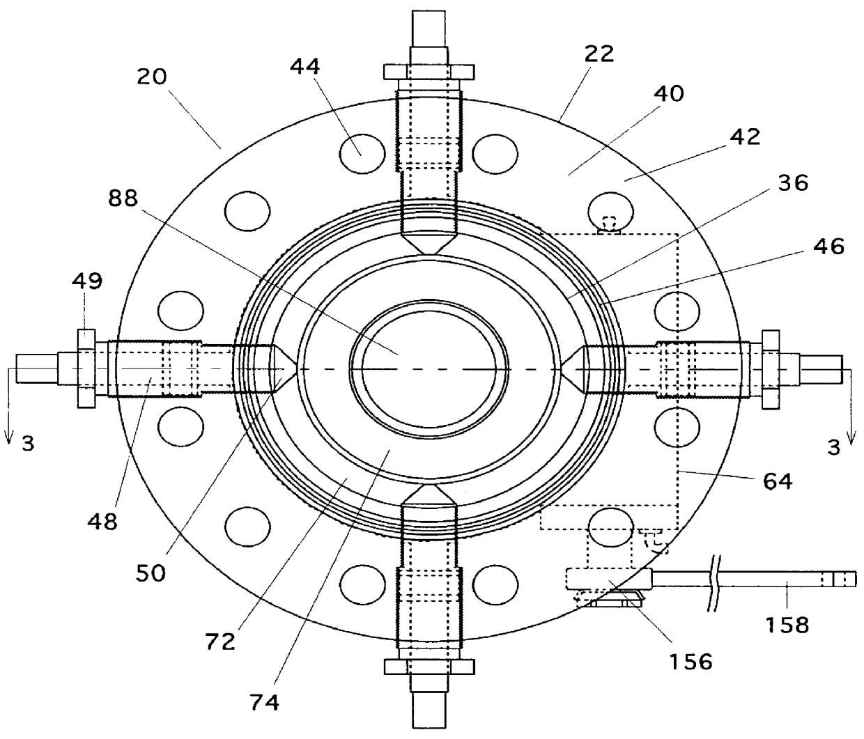
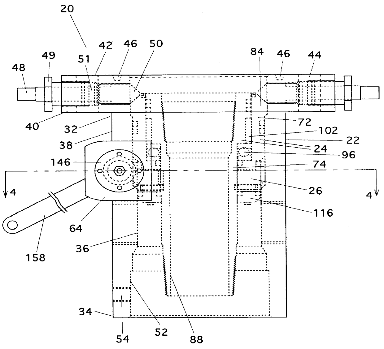
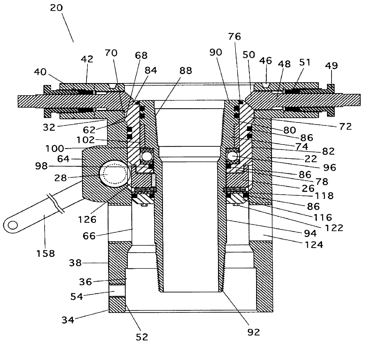
Referring to FIGS. 1-3, the within invention is directed at an apparatus (20) for attachment to a wellhead for suspending and rotating a tubing string contained within a wellbore. More particularly, the apparatus (20) combines the functions of a tubing head (22) and a tubing rotator in a single, integral unit. Further, referring to FIG. 9, the within invention is further directed at an improved tubing head (22) for attachment to the wellhead, which is able to accommodate the functional features or elements of a tubing rotator.

A typical wellhead is comprised of a plurality of components mounted at the ground surface above the wellbore. A rod or rod string is run through the wellhead and into the wellbore through a continuous fluid passage or pathway which extends through each of the components of the wellhead. The well may be produced by a reciprocating rod or tube, reciprocated by a pump jack or walking beam at the surface, or by a rotating rod or tube, driven by a rotary pump drive...


PUM


Abstract

A tubing head is provided for accommodating a rotator. The rotator includes a drive gear and a swivel tubing hanger which engages an internal surface of the tubing head and comprises a driven gear for engaging the drive gear. The tubing head defines a gear housing for the drive gear so that the drive gear may releasably engage the driven gear. The internal surface, gear housing and drive and driven gears are configured such that when the drive gear is in the gear housing, the tubing hanger engages the internal surface and the drive and driven gears are engaged, the tubing hanger may be removed from the tubing head by pulling it through the upper end without first disengaging the drive and driven gears. An apparatus is also provided comprising the tubing head, the swivel tubing hanger and the drive gear.

Description

The within invention relates to a tubing head designed to accommodate a tubing rotator therein such that the tubing head may be retrofit with the tubing rotator. Further, the within invention relates to an apparatus for attachment to a wellhead for suspending and rotating a tubing string within a wellbore, the apparatus comprising a tubing head and a tubing rotator combined to form a single, integral unit.A typical wellhead is often comprised of a casing head or a casing bowl which engages or is otherwise mounted to a casing string contained within a wellbore of a well at the surface. A tubing head or tubing bowl is mounted upon the upper surface of the casing head and provides a support mechanism for a tubing hanger. The tubing hanger is connected to or engages the upper end of the tubing string which is contained within the wellbore. Thus, the tubing hanger and the tubing string connected thereto are supported at the surface of the well by the tubing head. Alternately, the wellhea...

Claims


Application Information

Patent Timeline
IPC IPC(8): E21B33/03E21B33/04E21B43/12
CPCE21B33/0415E21B43/127
Inventor BLAND, LINDEN H.CAMPBELL, DAVID W.
Owner ROBBINS & MYERS ENERGY SYST
Why Eureka
Try Eureka