Fluid side contamination exclusion sealing lip for radial shaft seals

Inactive Publication Date: 2000-02-29
FREUDENBERG NOK GEN PARTNERSHIP
View PDF15 Cites 50 Cited by
  • Summary
  • Abstract
  • Description
  • Claims
  • Application Information

AI Technical Summary

Benefits of technology

One advantage of the present invention is that the exclusion sealing lip prohibits the ingestion of contaminates from the system fluid into the primary sealing lip area.
A further advantage of the present invention is that the venting feature of the exclusion sealing lip allows system fluid to transfer to the primary sealing lip thus establishing pressure equilibrium around the contaminate exclusion scaling lip.
Yet another advantage of the present invention is that it eliminates the need for additional components to be added to the radial shaft seal.
Another advantage of the present invention is that the dimensions and tolerances of the contaminate excl

Problems solved by technology

Many of these prior art excluder lips solve some problems but create others.
If the excluder lip is too loose then it is ineffective at keeping contaminates out of the primary sealing area.
Furthermore, if the excluder lip is too tight it will create excess heat which reduces actual operating time of the seal.
In

Method used


Image

  • Fluid side contamination exclusion sealing lip for radial shaft seals
  • Fluid side contamination exclusion sealing lip for radial shaft seals
  • Fluid side contamination exclusion sealing lip for radial shaft seals

Examples


Embodiment Construction

)

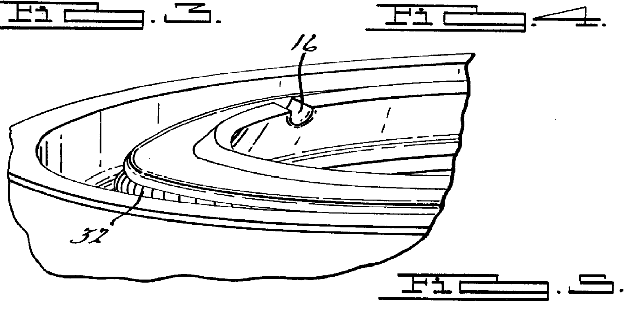
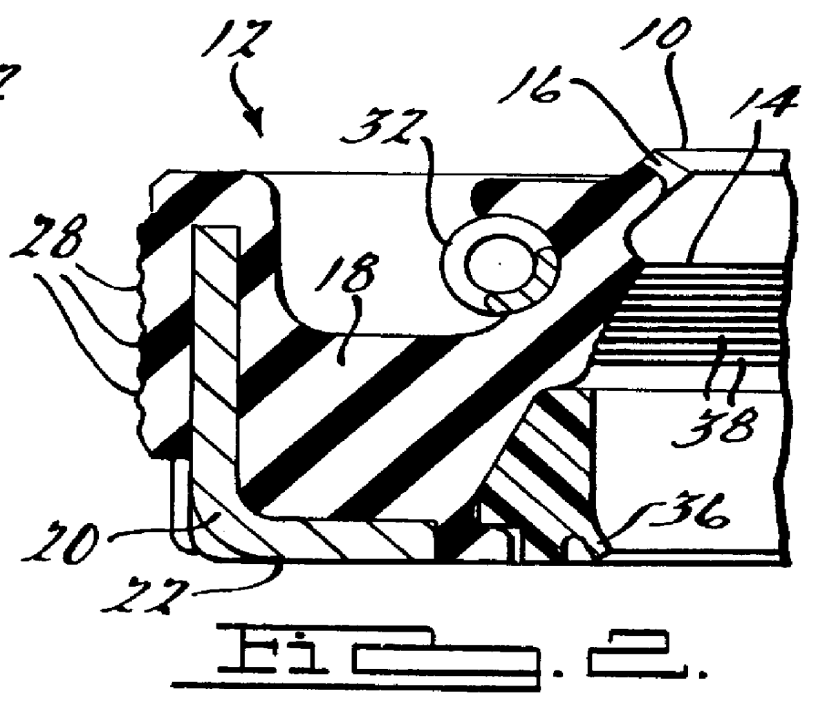
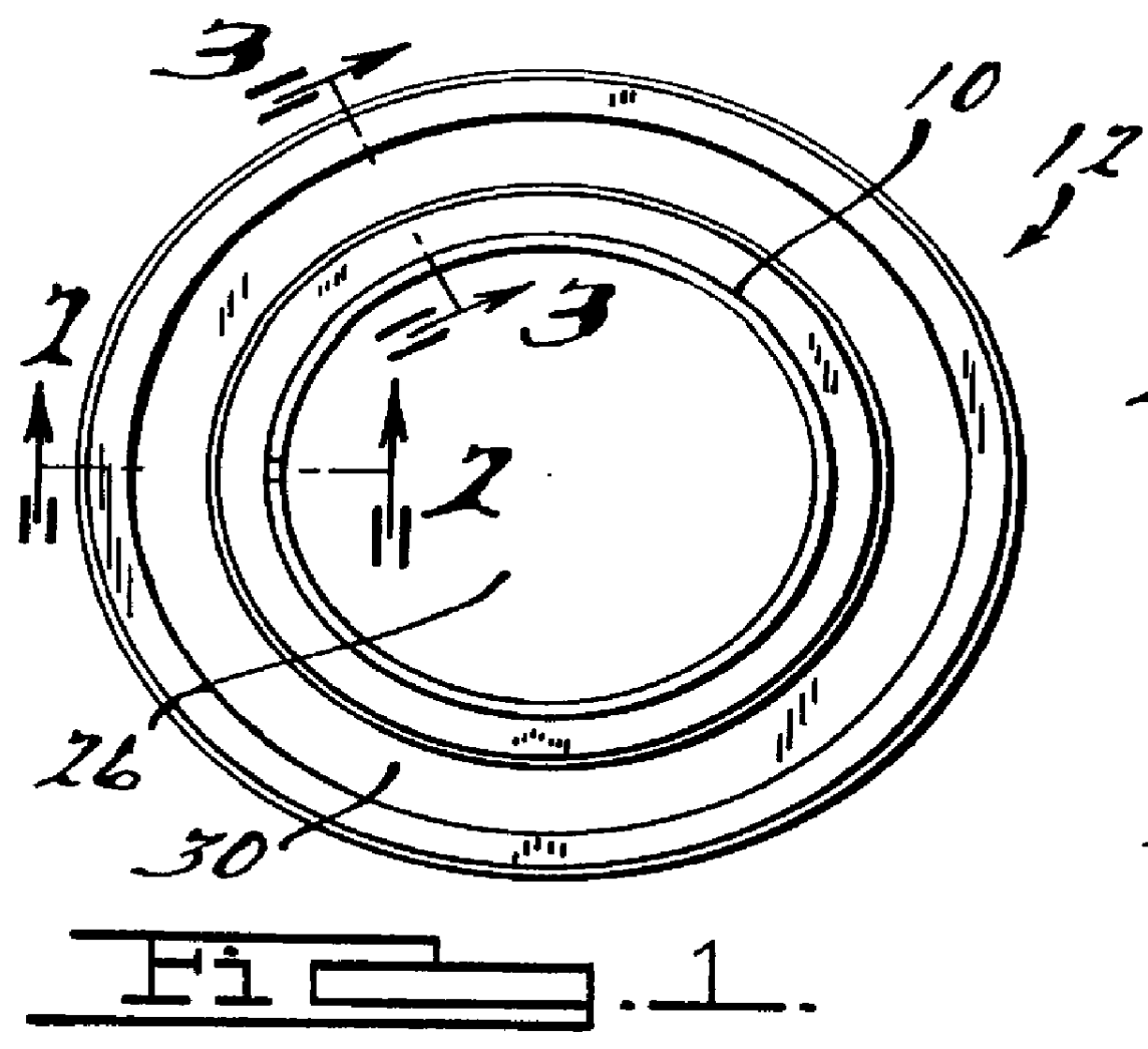
Referring to the drawings, a fluid side contamination exclusion sealing lip 10 for a radial shaft seal 12 is shown. The contaminate exclusion sealing lip 10 is integrally molded above the primary sealing lip 14 of a radial shaft seal 12. The contaminate exclusion sealing lip 10 is designed with a venting feature 16 which allows system fluid to transfer to the primary sealing lip 14, thus establishing pressure equilibrium around the contaminate exclusion sealing lip 10 when operating fluid pressure is applied to the system.

The radial shaft seal 12 as shown in FIGS. 1 through 5 includes a circumferential seal body 18 generally having a ring-like appearance. In the preferred embodiment the seal body 18 is made of an elastomer material however it should be noted that any other resilient rubber, plastic, or ceramic-like material may be used depending on the needs of the radial shaft seal 12. The radial shaft seal 12 also includes an insert member 20 which is molded directly into the out...


PUM


Abstract

A radial shaft seal for use on a shaft, said radial shaft seal including a rigid insert generally having a L-shaped cross section. The shaft seal including a circumferential seal body molded around the insert. The shaft seal further including an exclusion lip integral with the seal body, the exclusion lip having a venting mechanism. The venting mechanism allows fluid transfer into the primary sealing lip.

Description

1. Field of the InventionThe present invention relates to radial shaft seals, and more particularly to radial shaft seals that include a contamination exclusion sealing lip.2. Description of Related ArtRadial shaft seals have been known for years. Conventional seals include a rigid casing portion and an elastomeric seal lip. The seal lip includes a primary lip which is comprised of a pair of frusto-conical surfaces that include an oil and air side, these sides create a seal band to retain lubricant within the sealed region. The lubricant may be under pressure. Some of the prior art seals have also included an excluder or secondary lip. The use of this excluder lip is such that contaminates such as grit, dust, metal filings, etc are kept away from the immediate vicinity of the primary sealing lip so as not to create abrasion or otherwise to interfere with the sealing action or effect the seal life of the seal at the primary sealing lip. A typical excluder lip operates with little or ...

Claims


Application Information

Patent Timeline
IPC IPC(8): F16J15/32
CPCF16J15/322F16J15/324
Inventor DOWNES, MICHAEL
Owner FREUDENBERG NOK GEN PARTNERSHIP
Why Eureka
Try Eureka