

Medicament dispenser
- Summary
- Abstract
- Description
- Claims
- Application Information
AI Technical Summary
Benefits of technology
Problems solved by technology
Method used
Image

Examples
Embodiment Construction
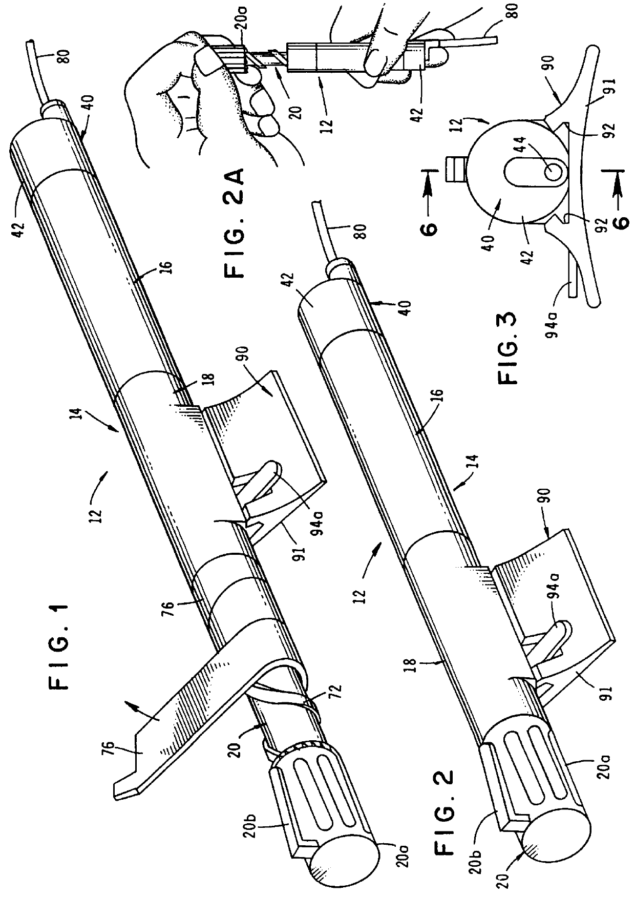
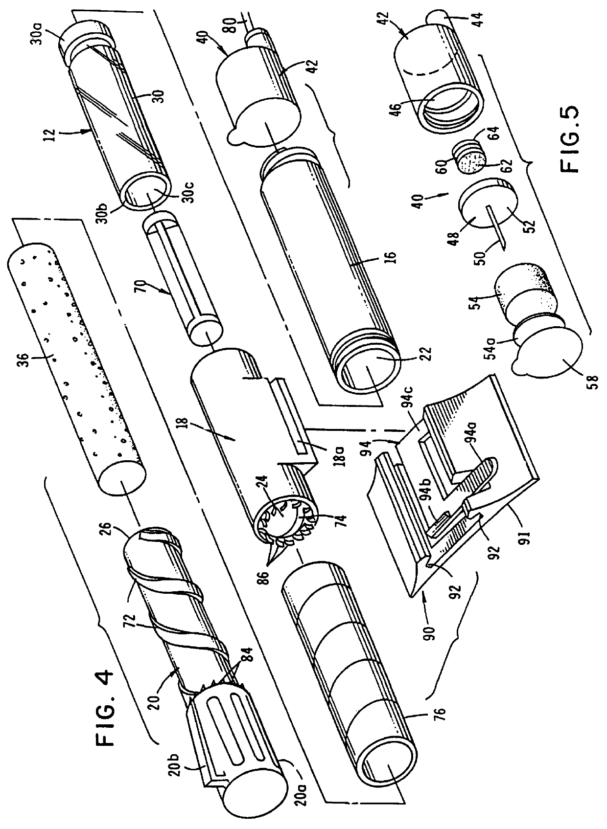
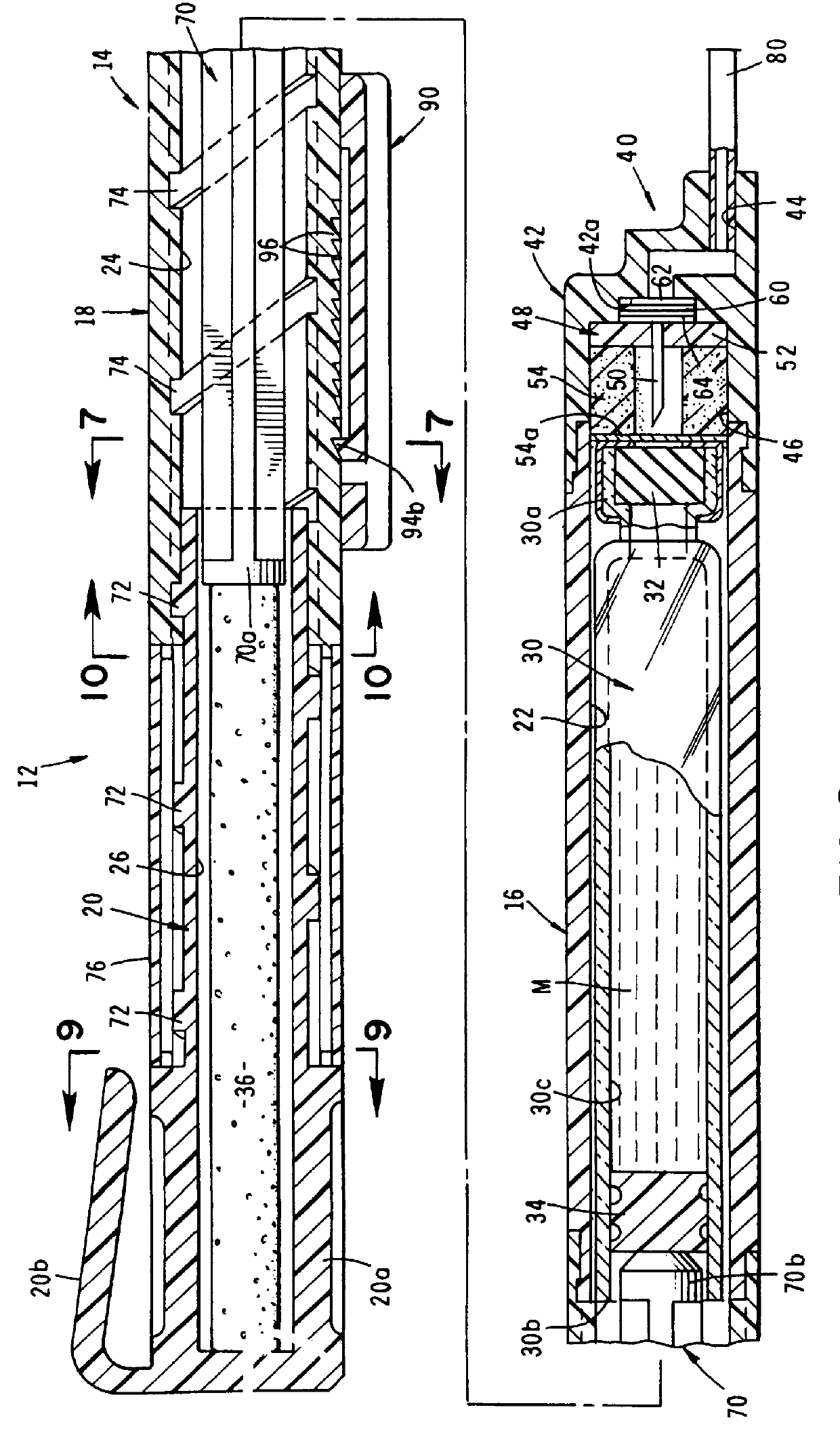
Referring to the drawings and particularly to FIGS. 1 through 5, one embodiment of the dispensing apparatus of the present invention is there illustrated and generally designated by the numeral 12. The apparatus of this form of the invention comprises an elongated body 14, which is made up of three interconnected, generally tubular shaped portions 16, 18, and 20 respectively, portion 20 comprising the operating means of the invention, the purpose of which will presently be described. As best seen by referring to FIG. 6, when portions 16, 18, and 20 are interconnected to form elongated body 14, they define first, second and third communicating interior chambers 22, 24, and 26 respectively.
Removably receivable within first chamber 22 is a prefilled medicament vial 30 having a first end 30a sealed by a piercable member 32 and a second end 30b sealed by an elastomeric plunger 34 which is telescopically movable longitudinally of the internal fluid reservoir or chamber 30c of vial 30. Pie...
PUM
 Abstract
Description
Claims
Application Information