Rendering method and apparatus

a technology of a device and a rendering method, applied in the field of computer graphics, can solve the problems of reflection mapping, large distortion, inaccurate global hidden relationship,

Inactive Publication Date: 2000-03-07
GOOGLE LLC
View PDF3 Cites 82 Cited by
  • Summary
  • Abstract
  • Description
  • Claims
  • Application Information

AI Technical Summary

Problems solved by technology

However, since the reflection map is made around a certain point in space, it has the inherent problem that the distortion becomes larger as going away from the point and that a global hidden relationship also becomes inaccurate.
Particularly, in OpenGL, the reflection mapping, where texture coordinates are automatically generated by a sphere, has another problem.
That is, there is the problem that (1) all directions (stereoscopic angle 720.degree.) cannot be covered, (2) distortion is large in the vicinity of the equator of a sphere, and (3) reflection vectors are generated only with a view point coordinate system.
Furthermore, there is the disadvantage that a view point cannot be moved in real time.
However, because the hardware is special hardware, it cannot be used by users who have been familiar with API such as OpenGL.

Method used


Image

  • Rendering method and apparatus
  • Rendering method and apparatus
  • Rendering method and apparatus

Examples


Embodiment Construction

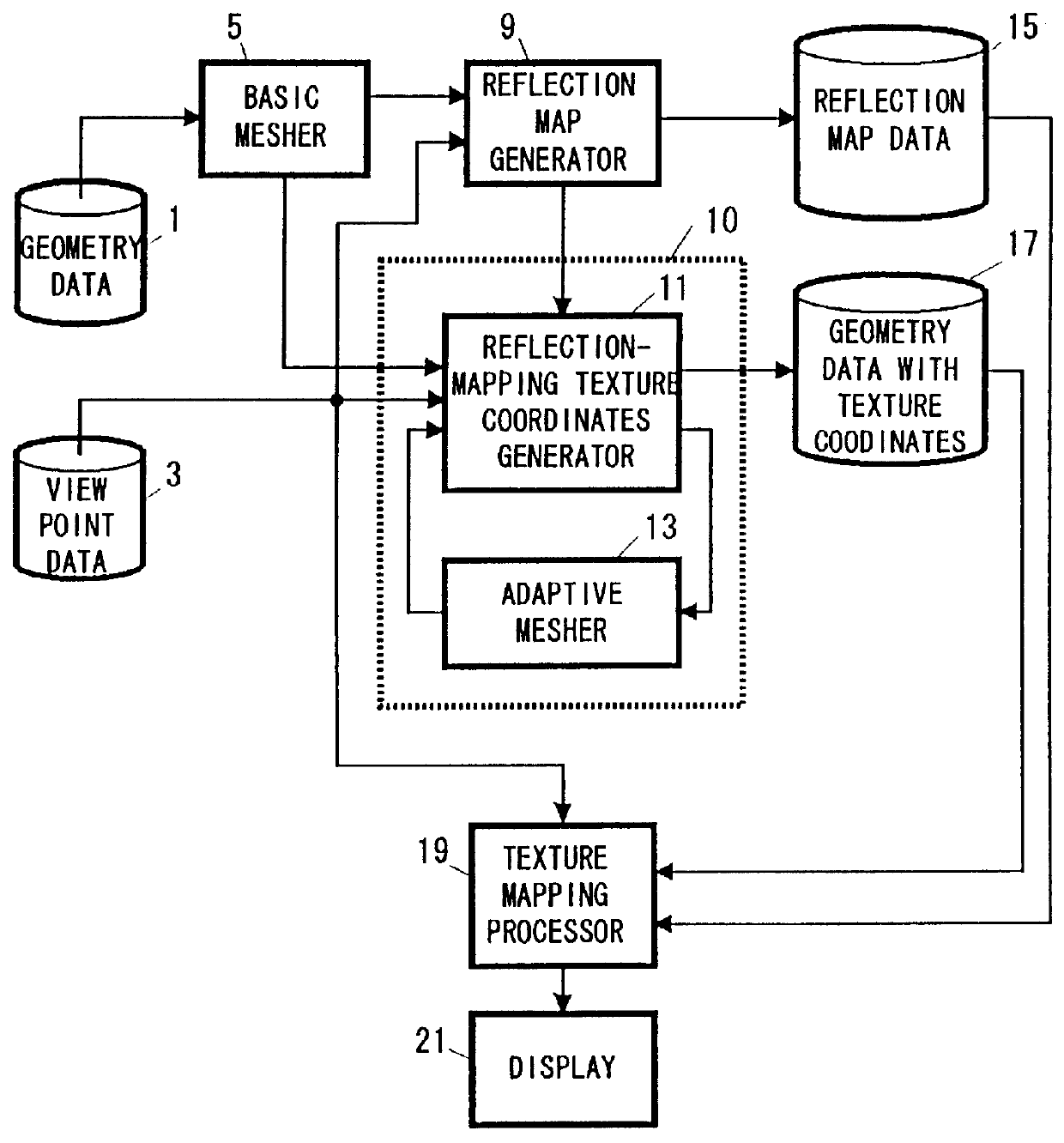
With respect to the method of the present invention directed to rendering a three-dimensional space which includes an object with a mirror, as described above, when the coordinates of the image are checked, it is inspected whether the surfaces where the intersecting point exists are all identical for each vertex of a certain polygonal element. The reason why this check is performed is that, if all surfaces are not identical, the region of the image (coordinates in the region) for mapping cannot be specified with only the information obtained up to this. Therefore, when all surfaces are not identical, the polyhedron is clipped by a polygonal pyramid whose apex is the predetermined point and whose ridgeline is the reflection vector of each vertex of the certain polygonal element, and a reflection vector on a boundary line of each surface of the polyhedron is calculated. Then, the coordinate in the rendered image, which corresponds to the reflection vector on the boundary line, is calc...


PUM


Abstract

The present invention is directed to a real-time controllable reflection mapping function which covers all stereoscopic directions of space. More specifically, the surface of a mirrored object is segmented into a plurality of polygonal elements (for example, triangles). Then, a polyhedron, which includes a predetermined point (for example, the center of the mirrored object) in a three-dimensional space (for example, a cube) in the interior thereof, is generated and a rendering process is performed for each surface of the polyhedron with the predetermined point as a view point. The rendered image is stored. Thereafter, a reflection vector is calculated between each vertex of the polygonal elements and a view point used when the entire three-dimensional space is rendered. Next, the surface of the polyhedron, in which an intersecting point between the reflection vector with the predetermined point as a start point and the polyhedron exists, is obtained. The coordinate in the image, which corresponds to each vertex of the polygonal elements, is calculated by using the surface where the intersecting point exists and the reflection vector. The image is texture-mapped onto the surface of the object by using the coordinate in the image which corresponds to each vertex of the polygonal elements. Finally, the result of the texture mapping is displayed.

Description

1. Technical FieldThe present invention relates to a rendering method which uses texture mapping in the field of computer graphics, and more particularly to a rendering method where reflection mapping (also called environment mapping) is applied when a three-dimensional space including an object with a mirror is given.2. Prior ArtThe reflection mapping in VRML (for example, version 2.0), in addition to the OpenGL (trademark of Silicon Graphics Inc.) of a graphic API (application program interface) being now most extensively used, has been positioned as an important reality enhancement method which simply simulates "mirroring" at high speed. The reflection mapping is one of the texture mapping methods and simulates global reflection effects by accessing textures with reflection vectors which are dynamically determined for each vertex together with the movement of a view point, instead of accessing textures with static texture coordinates appendant to the vertices of an object (for ex...

Claims


Application Information

Patent Timeline
Patent Type & Authority Patents(United States)
IPC IPC(8): G06T15/10G06T15/00G06T15/04
CPCG06T15/10
Inventor AONO, MASAKIOHBUCHI, RYUTAROUSHIMIZU, KAZUYA
Owner GOOGLE LLC
Why Eureka
Try Eureka