Spindle for gripping and closing a mounting member

Inactive Publication Date: 2000-03-14
HARDINGE INC
View PDF31 Cites 19 Cited by
  • Summary
  • Abstract
  • Description
  • Claims
  • Application Information

AI Technical Summary

Benefits of technology

The spindle of the present invention thus includes a hydrostatic thrust bearing which provides a high level of performance and reliability, while the axially movable rotary member and actuating assembly provide the advantage of permitting the mounting member to be positively closed. In addition, the integral drive motor eliminates the need for a belt drive where appropriate and enhances acceleration and responsiveness of the spindle. Further advantages are provided by the preferred through-hole drawbar, which allows lengthy workpieces to be mounted with a portion extending through the drawbar, thereby increasing the range of stock which may be held in the mounting member.

Problems solved by technology

Heretofore known spindles with fluid thrust bearings have, however, not included satisfactory capability for drawbar-operated closing of mounting members as described above, which requires that the drawbar be movable axially so as to draw the mounting member against the tapered contacting surface.
The combined capability of rotary and axial movement has proven difficult to advantageously achieve in spindles with fluid bearings.
Such an arrangement may have disadvantages in that the belt adds additional inertial drag to the spindle, thereby reducing the ability of the spindle to accelerate quickly to a desired speed, or to decelerate when desired.
Moreover, failure of the belt will, of course, render the spindle inoperable until repairs can be made, and the maximum speed capacity of the belt also limits the overall performance of the spindle.
The advantages of integral drive motors, which eliminate drive belts, have not been fully realized in a spindle having a fluid bearing.

Method used


Image

  • Spindle for gripping and closing a mounting member
  • Spindle for gripping and closing a mounting member
  • Spindle for gripping and closing a mounting member

Examples


Embodiment Construction

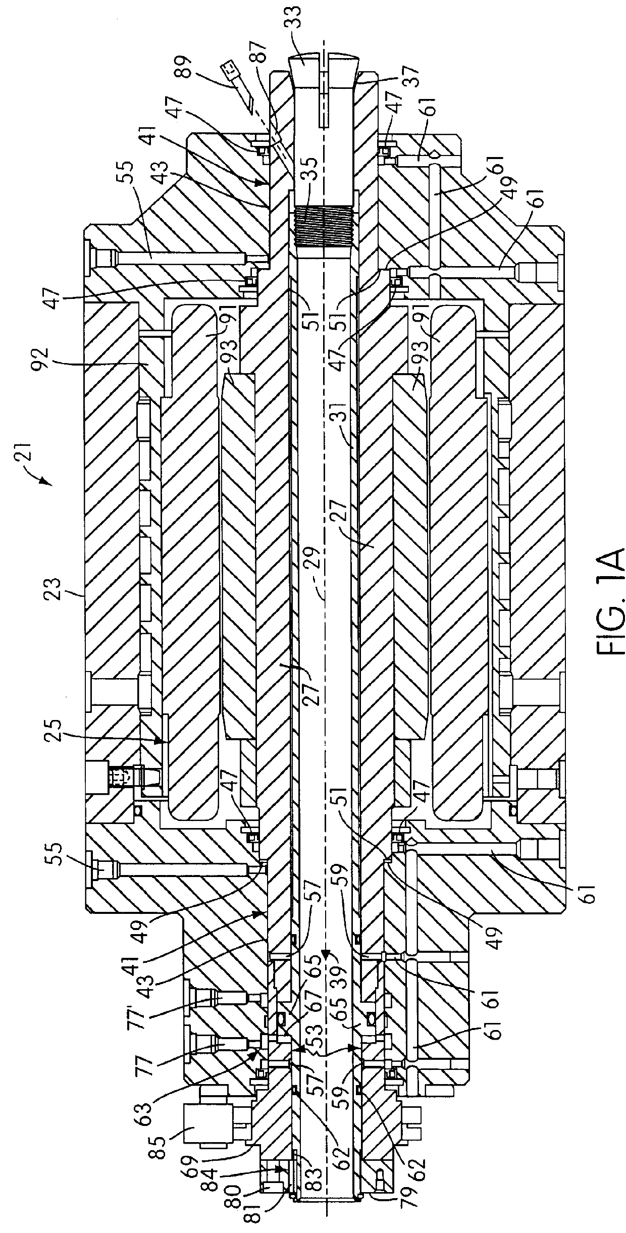
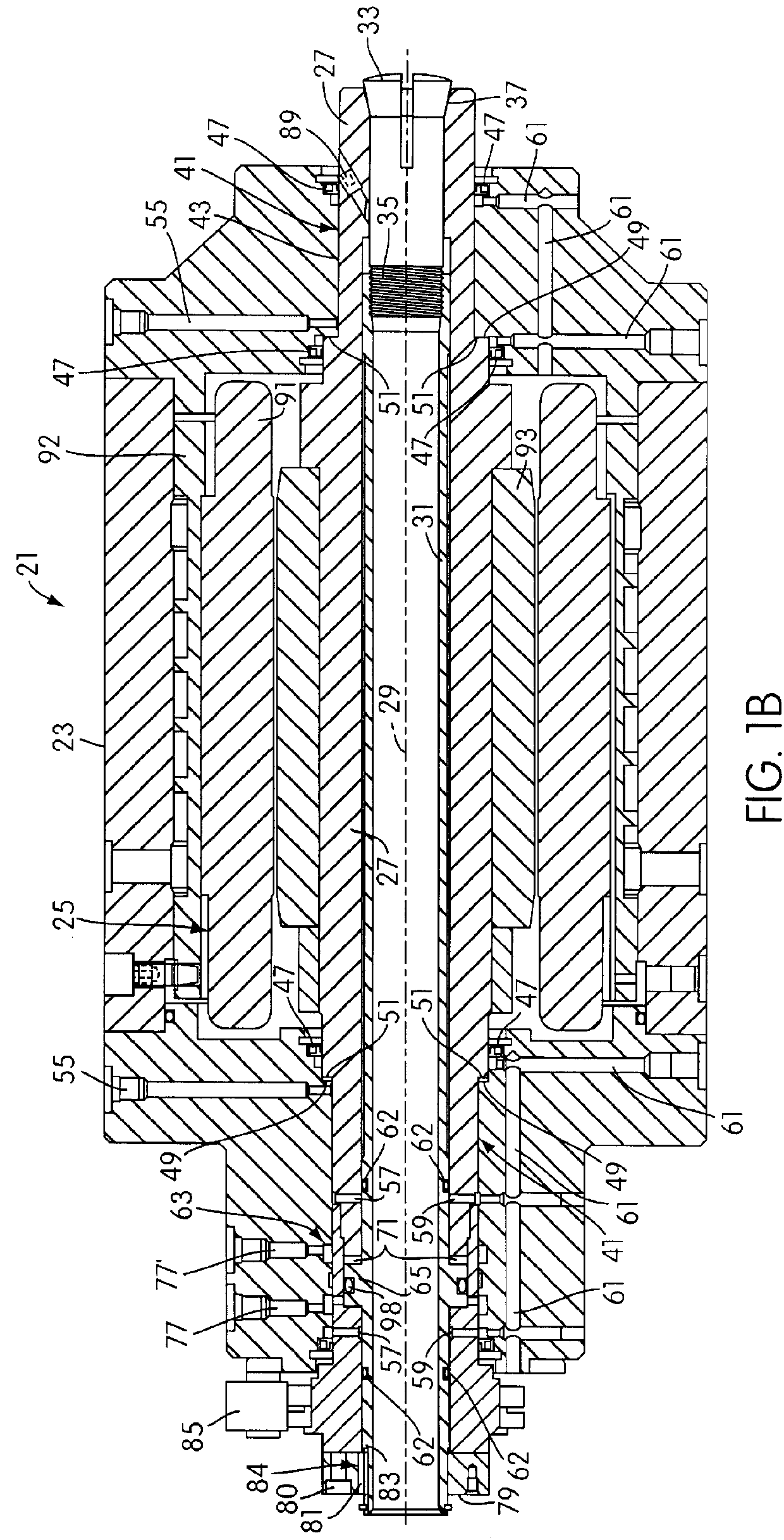
As shown in FIG. 1, a preferred embodiment of a spindle for gripping and closing a mounting member in accordance with the present invention is designated generally by the reference character 21. The spindle 21 includes a housing 23 in which is mounted an electric integral spindle drive motor 25, which will be described in more detail presently.

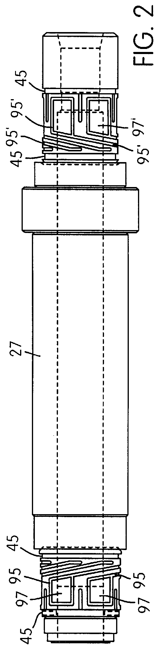
A hollow spindle shaft 27 is supported within the housing 23, as will be described shortly, for rotation about its longitudinal axis 29. Received within the hollow spindle shaft 27 is a hollow through-hole drawbar 31 which is supported for rotation about the longitudinal axis 29 and, as will again be described shortly, for axial movement relative to the spindle shaft 27. The drawbar 31 therefore forms a first rotary member, and the spindle shaft 27 forms a second rotary member disposed about the drawbar 31 in coaxial relation thereto, and together the drawbar 31 and the spindle shaft 27 form a spindle assembly.

A mounting member in the form of ...


PUM

PropertyMeasurementUnit
Pressureaaaaaaaaaa
Flow rateaaaaaaaaaa

Abstract

A spindle for gripping and closing a mounting member which includes a housing having a spindle assembly mounted therein including a first rotary member capable of rotation about its longitudinal axis and a second rotary member disposed about the first rotary member in coaxial relation and being capable of rotation about the longitudinal axis. The first rotary member has a gripping portion for gripping the mounting member and the second rotary member has a thrust surface and a contacting portion for contacting the mounting member. A radial bearing in the housing supports the second rotary member, and a fluid thrust bearing supports the thrust surface of the second rotary member. One of the first and second rotary members is capable of axial movement relative to the other rotary member and has an engagement surface engageable for causing axial movement of the axially moveable rotary member. An actuating assembly is provided to selectively engage the engagement surface to move the axially movable rotary member relative to the other rotary member to draw the mounting member against the contacting surface for closure.

Description

1. Field of the InventionThe present invention relates to spindles and, in particular, to a spindle for gripping and closing a mounting member.2. Description of the Related ArtSpindles are widely used for providing rotary motion to workpieces and / or tools in many applications, including tool making, machining, and general industrial production. Ordinarily, a mounting member such as a slotted collet or the like will be provided for mounting the workpiece or tool to be rotated on the spindle. The spindle must, therefore, include some provision for gripping and closing the mounting member to hold the workpiece or tool, and this requirement is typically met by providing a drawbar threaded to engage the mounting member or collet. The drawbar can then be moved along its axis to draw the collet against a tapered contacting surface and thereby contract the slotted collet around the workpiece or tool to hold it securely.In order to improve the performance of spindles, fluid bearings, which a...

Claims


Application Information

Patent Timeline
IPC IPC(8): B23B31/20
CPCB23B31/205Y10T409/309352Y10T279/1258B23B31/207B23B31/2073B23B2270/025
Inventor SHEEHAN, BRIAN C.SHEEHAN, TERRY M.SOROKA, DAN P.
Owner HARDINGE INC
Why Eureka
Try Eureka