Pixel image enhancement system and method

a pixel image and enhancement system technology, applied in the field of pixel image enhancement system and method, can solve the problems of high error-prone analysis of only a 3 by 3 pixel matrix, and unfavorable image quality improvement, so as to improve image quality and image quality, the effect of reducing memory and processing requirements

Inactive Publication Date: 2000-03-14
CSR TECH INC
View PDF3 Cites 143 Cited by
  • Summary
  • Abstract
  • Description
  • Claims
  • Application Information

AI Technical Summary

Benefits of technology

It is a further object of this invention to provide such a pixel image enhancement system and methodology which lowers the video subsystem cost.
It is a further object of this invention to provide such a pixel image enhancement system and methodology which lowers memory and processing requirements.
This invention results from the realization that a high resolution pixel image enhancement system can be accomplished, not by analyzing a central pixel of a small matrix of input pixels using templates or tables of standard pixel formats, but by detecting elemental edges between adjacent input pixels, generating an edge map, and using Boolean equations implemented in hardware to produce a segment of an inferred edge, within an output cell area, from the edge map resulting in higher resolution and accuracy than the inputted pixel map would otherwise allow. The result is a system which enhances color as well as black and white alphanumeric and graphic images and which can be used in conjunction with any type of display device: printers, CRTs, LCD displays, projection displays, television, facsimile machines and the like at a much lower cost. An unwieldy number of patterns or templates need not be designed and the system can be implemented on a chip which is placed in the output device or elsewhere for very high resolution.

Problems solved by technology

A close inspection of letters and graphic images on a computer screen or a hard copy print out reveal jagged lines causing an unsightly rough appearance of displayed and printed images.
One disadvantage in the prior art is the use of "standard pixel formats" and templates.
The analysis of only a 3 by 3 pixel matrix is very error prone, however, since the pattern analyzed can be indicative of a line angled at 45.degree. or the beginning of a curve.
Analyzing a larger subset of the input pixel matrix requires the formation of a very large unwieldy number of standard pixel formats or templates.
Such tri-valued templates, however, are still very limited.
Although it may be fairly straight forward to straighten out a jagged 45.degree. line according to this prior methodology, it is nearly impossible to use standard pixel formats or templates to account for the numerous possible permutations of angled lines, curves, and other features inherent in the display of alpha numeric characters and graphical displays.
Anti-aliasing filters remove spurious a high frequency information which is an artifact of the quantization process but they do not replace the spurious high frequency information with inferred hypothetical high frequency information.

Method used


Image

  • Pixel image enhancement system and method
  • Pixel image enhancement system and method
  • Pixel image enhancement system and method

Examples


Embodiment Construction

Other objects, features and advantages will occur to those skilled in the art from the following description of a preferred embodiment and the accompanying drawings, in which:

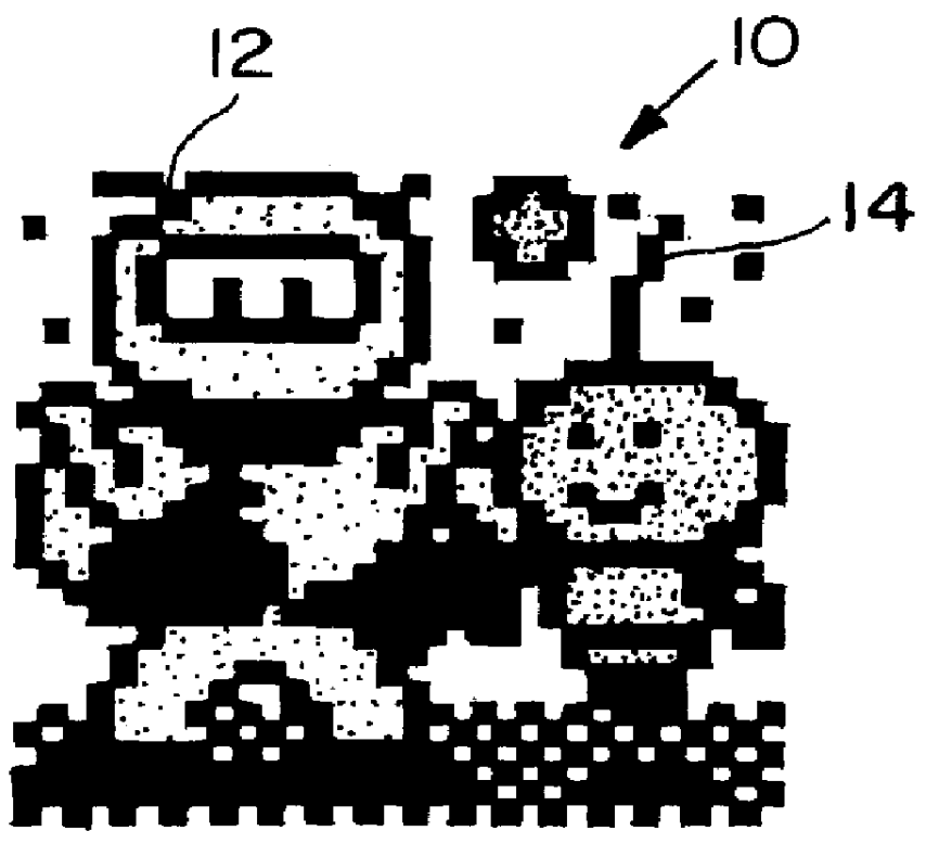
FIG. 1 is a graphical depiction of a low resolution pixel image;

FIG. 2 is a graphical depiction of the low resolution pixel image shown in FIG. 1 after it is enhanced in accordance with the system and methodology of this invention;

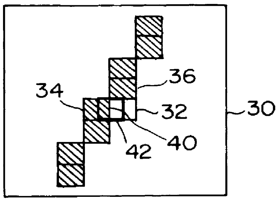
FIG. 3A is a view of a window containing a set of input pixels in accordance with this invention;

FIG. 3B is a view of a partial inferred edge created within an output cell overlapping two adjacent input pixels within the window shown in FIG. 3A in accordance with this invention;

FIG. 4 is a view of a jagged line resulting from the low resolution input pixels shown in FIG. 3A;

FIG. 5 is a view of the same line created from the inferred edges produced in accordance with this invention as shown in FIG. 3B;

FIG. 6 is a block diagram of the major subcomponents of the pixel image enhancement s...


PUM


Abstract

A pixel image enhancement system which operates on color or monochrome source images to produce output cells the same size as the source pixels but not spatially coincident or one-to-one correspondent with them. By operating upon a set of input pixels surrounding each output cell with a set of logic operations implementing unique Boolean equations, the system generates "case numbers" characterizing inferred-edge pieces within each output cell. A rendering subsystem, responsive to the case numbers and source-pixel colors, then produces signals for driving an output device (printer or display) to display the output cells, including the inferred-edge pieces, to the best of the output device's ability and at its resolution.

Description

A pixel image enhancement system for higher resolution black and white and color images including alphanumeric characters and graphic video game designs displayed on such devices such as computer monitors, printers, facsimile machines, television screens, video game displays, and the like.BACKGROUND OF INVENTIONA need for higher resolution image production is well documented in the art. A close inspection of letters and graphic images on a computer screen or a hard copy print out reveal jagged lines causing an unsightly rough appearance of displayed and printed images.One method of ameliorating this problem, disclosed in U.S. Pat. No. 4,437,122 to the Xerox Corporation involves isolating a center pixel, matching the 3 by 3 pixel pattern surrounding and including the center pixel with a table of "standard pixel formats", and then subdividing the center pixel area into enhanced "subpixels".Another method utilizes pattern matching templates operating on a window with a central bit. See...

Claims


Application Information

Patent Timeline
Patent Type & Authority Patents(United States)
IPC IPC(8): H04N1/409H04N1/40
CPCH04N1/40068H04N1/4092
Inventor CARLEY, ADAM
Owner CSR TECH INC
Why Eureka
Try Eureka