Frost detecting device

a detection device and detecting technology, applied in the direction of defrosting, cooling apparatus, instruments, etc., can solve the problems of reducing cooling efficiency, increasing energy consumption, and inability to control the condition of frosting

Inactive Publication Date: 2000-03-21
ISHIZUKI ELECTRONICS
View PDF19 Cites 5 Cited by
  • Summary
  • Abstract
  • Description
  • Claims
  • Application Information

AI Technical Summary

Problems solved by technology

Frost on the surface of the cooling fan of a heat exchanger incorporated into a refrigerator reduces the cooling efficiency.
A continuous operation with the frost uneconomically increases energy consumption, and often causes failure.
Although the start of defrosting can be controlled in the above method, the frosting condition cannot be controlled, because it changes depending on ambient temperature, humidity, frequency of opening the door, and the conten

Method used


Image

  • Frost detecting device
  • Frost detecting device
  • Frost detecting device

Examples


Embodiment Construction

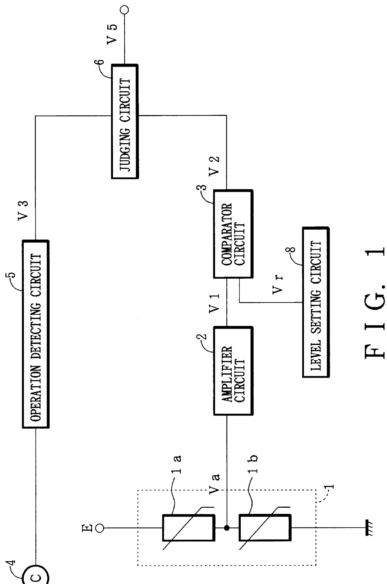
The following is a description of one embodiment of a frost detecting device of the present invention, with reference to the accompanying drawings. FIG. 1 is a circuit diagram illustrating the embodiment of the frost detecting device of the present invention in FIG. 1, the frost detecting device comprises a frost detector 1, an amplifier circuit 2 for amplifying an output signal transmitted from the frost detector 1, a comparator circuit 3 for comparing the output of the amplifier circuit 2 with a set level (reference voltage) determined depending on the amount of frost, a level setting circuit 8 for generating the set level (reference voltage) supplied to the comparator circuit 3, an operation detecting circuit 5 for detecting a halt of operation of a compressor and a cooling fan 4, and a judging circuit 6 for detecting frost in accordance with the operations of the compressor and the cooling fan 4.

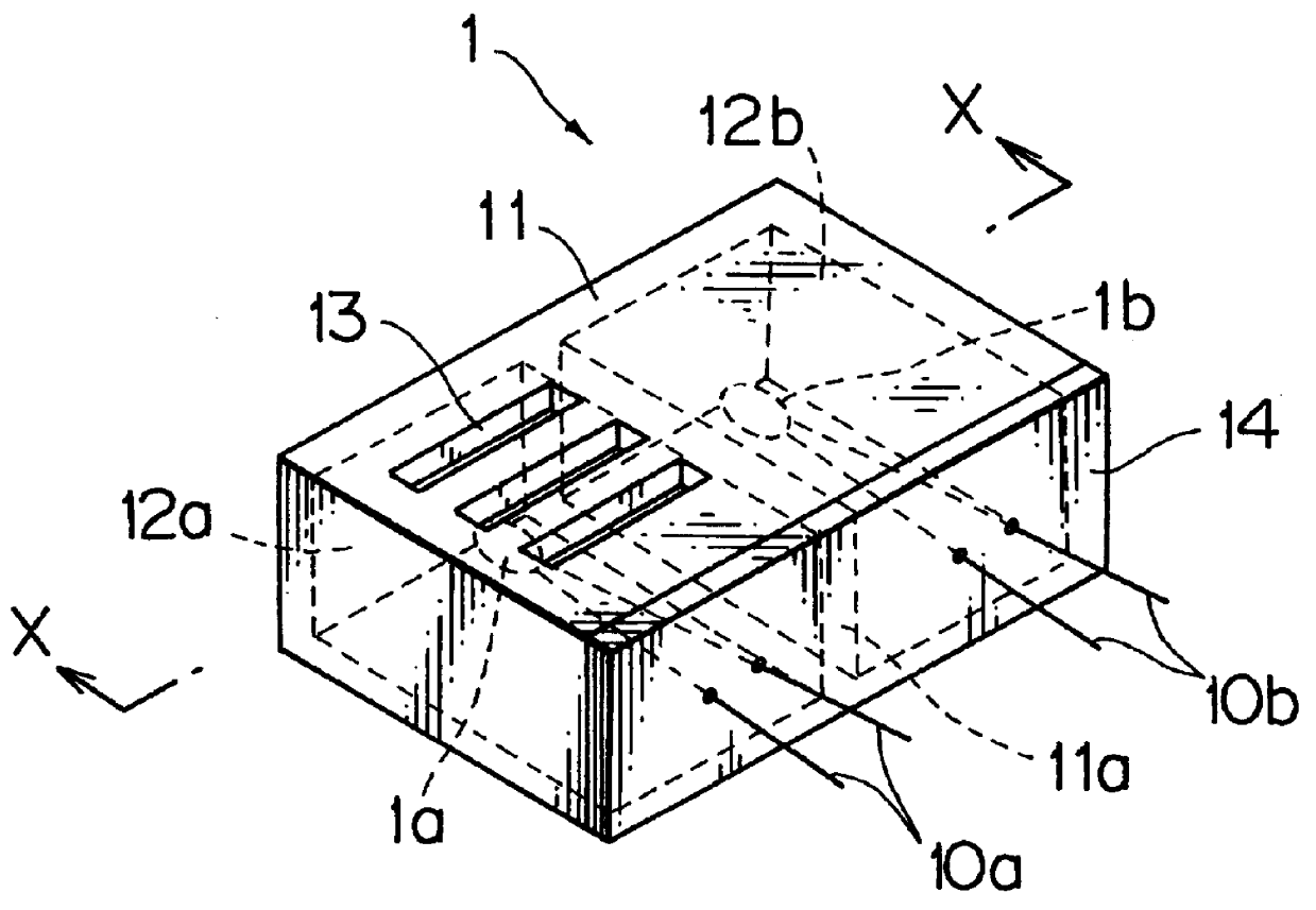
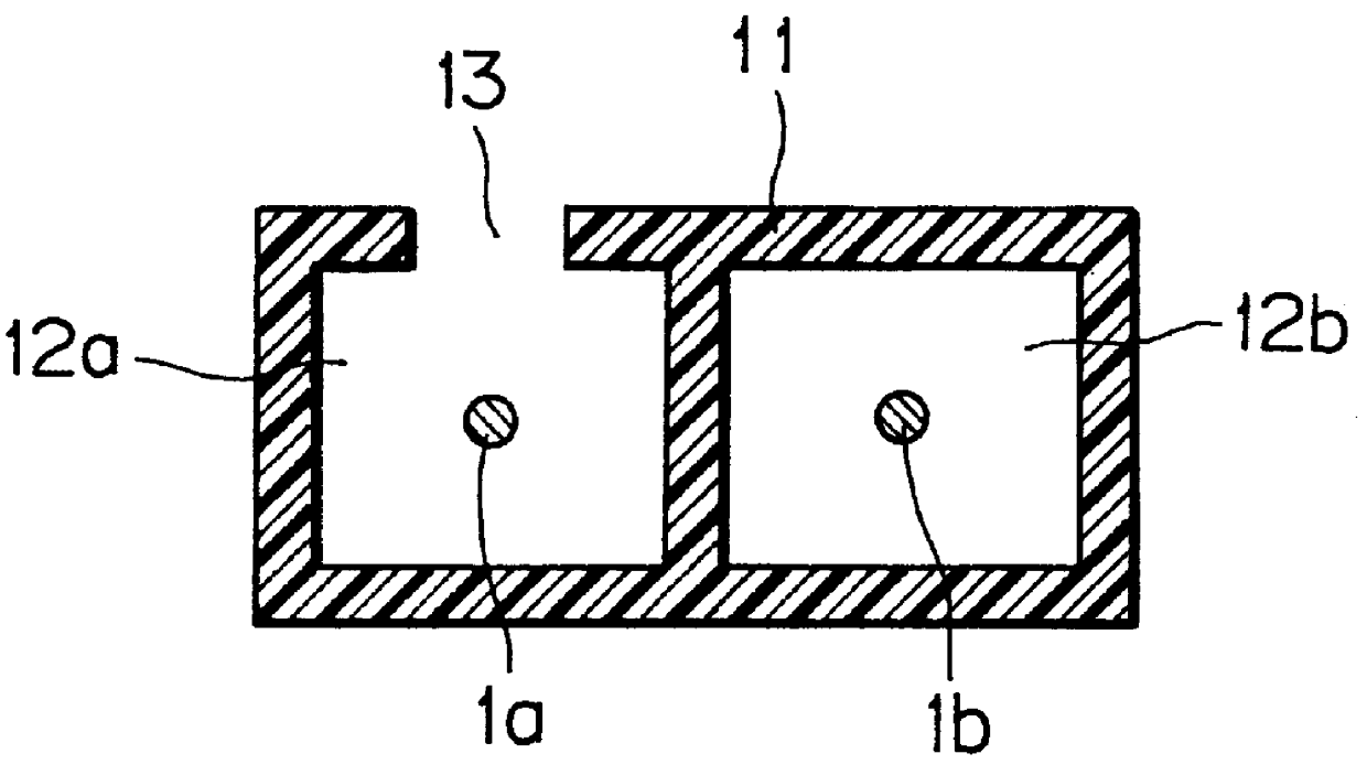
FIG. 2A is a perspective view of the frost detector 1, and FIG. 2B is a sectional vi...


PUM


Abstract

PCT No. PCT/JP96/03486 Sec. 371 Date Jun. 12, 1998 Sec. 102(e) Date Jun. 12, 1998 PCT Filed Nov. 28, 1996 PCT Pub. No. WO97/24568 PCT Pub. Date Jul. 10, 1997A frost detecting device including a frost detector which detects the amount of frost from the temperature difference between a detecting thermal sensitive element and a compensating thermal sensitive element is provided. The frost detecting device includes: a frost detector 1 made up of a detecting thermal sensitive element and a compensating thermal sensitive element; an amplifier circuit 2 for amplifying an output signal from the frost detector 1; a comparator circuit 3 for comparing an output voltage from the amplifier circuit 2 with a set level; an operation detecting circuit 5 for detecting operating conditions of a compressor and a cooling fan 4; and a judging circuit 6 for detecting the amount of frost in accordance with output voltages from the operation detecting circuit 5 and the comparator circuit 3. The output from the comparator circuit 3 is used to detect the amount of frost only when the compressor and the cooling fan 4 are both in operation.

Description

1. Field of the InventionThe present invention relates to a frost detecting device used in various industrial machines and refrigerators.2. Related ArtFrost on the surface of the cooling fan of a heat exchanger incorporated into a refrigerator reduces the cooling efficiency. A continuous operation with the frost uneconomically increases energy consumption, and often causes failure. In view of this, a frost detecting method generally used includes the steps of: switching on and off the compressor by detecting the inner temperature of a refrigerator; cooling for a predetermined period of time using a timer; after the cooling is performed for a predetermined period of time, switching to a heating operation to defrost; and, after the defrosting for a predetermined period of time, stopping the heating operation.Although the start of defrosting can be controlled in the above method, the frosting condition cannot be controlled, because it changes depending on ambient temperature, humidity,...

Claims


Application Information

Patent Timeline
IPC IPC(8): F25D21/02F25D21/00
CPCF25D21/02F25D21/00
Inventor NOJIRI, TOSHIYUKISAITO, SHINICHI
Owner ISHIZUKI ELECTRONICS
Why Eureka
Try Eureka