Circular-polarization antenna

a circular polarization antenna and antenna technology, applied in the direction of polarised antenna unit combinations, printed circuit non-printed electric components association, instruments, etc., can solve the problems of high mounting cost, difficult to reduce the height of the circular polarization antenna as a whole, and unlikely to reduce the mounting cost. , to achieve the effect of low mounting cos

Inactive Publication Date: 2000-03-21
MURATA MFG CO LTD +1
View PDF7 Cites 57 Cited by
  • Summary
  • Abstract
  • Description
  • Claims
  • Application Information

AI Technical Summary

Benefits of technology

Accordingly, it is an object of the present invention to provide a low-cost, low-pro

Problems solved by technology

In addition, since components are required to be mounted on both surfaces of the mounting substrate 101, mounting cost is high.
Therefore, it is difficult to reduce the he

Method used


Image

  • Circular-polarization antenna
  • Circular-polarization antenna
  • Circular-polarization antenna

Examples


Embodiment Construction

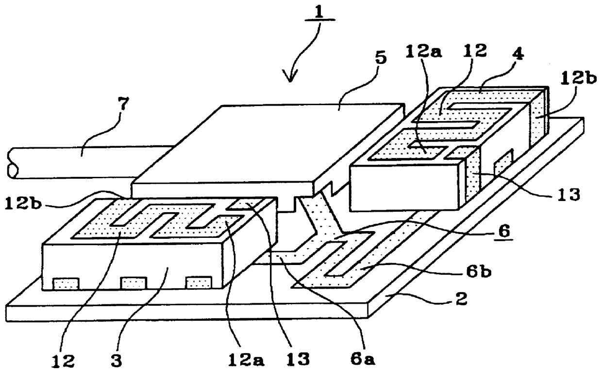
FIG. 1 is a circular-polarization antenna according to an embodiment of the present invention. In FIG. 1, the circular-polarization antenna 1 includes a mounting substrate 2, surface-mount antennas 3 and 4 mounted on the second major surface of the mounting substrate 2, a shield case 5 for covering an amplification circuit (not shown) mounted on the second major surface of the mounting substrate 2, a phase circuit 6 for connecting the amplification circuit to the surface-mount antennas 3 and 4, and a cable 7 connected to the amplification circuit at one end. There is nothing mounted on the first major surface of the mounting substrate 2. The surface-mount antennas 3 and 4 have the same structure and, as described later, are disposed such that their longitudinal directions are perpendicular to each other in order that their planes of polarization are perpendicular to each other in the direction normal to the mounting surface of the mounting substrate 2. The phase circuit 6 is formed ...


PUM


Abstract

The invention provides a low-profile circular-polarization antenna that can be implemented at a reduced mounting cost of components. Two linear-polarization surface-mount antennas are mounted on a mounting substrate such that their planes of polarization are perpendicular to each other in the direction normal to the mounting surface, and an amplification circuit, a shield case for covering the circuit, and a phase circuit for sending signals having the same amplitude and a phase difference of 90 degrees to the two surface-mount antennas are provided on the same mounting surface.

Description

1. Field of the InventionThe present invention relates to circular-polarization antennas, and more particularly, to a compact low-profile circular-polarization antenna such as a GPS antenna used for car-mounted and portable navigation systems. The present invention further relates to a radio apparatus using the circular-polarization antenna.2. Related Art of the InventionFIG. 17 shows a conventional circular-polarization antenna. The circular-polarization antenna is of a microstrip patch type.In FIG. 17, the circular-polarization antenna 100 includes a mounting substrate 101, a patch antenna 102 mounted on the second major surface of the mounting substrate 101, a shield case 103 for covering an amplification circuit (not shown) mounted on the first major surface of the mounting substrate 101, and a cable 104 connected to the amplification circuit at one end. The patch antenna 102 is made from a dielectric substrate such as ceramic and resin. A ground electrode is formed on the whole...

Claims


Application Information

Patent Timeline
IPC IPC(8): H01Q1/36H01Q1/38H01Q21/24H05K3/34H05K1/18G01S19/36H01Q1/24H01Q1/52H01Q13/08H01Q23/00
CPCH01Q1/36H01Q1/38H01Q21/24H05K1/181H05K3/3442
Inventor KUSHIHI, YUICHISHIKATA, MASARU
Owner MURATA MFG CO LTD
Why Eureka
Try Eureka