Driving circuit for driving simple matrix type display apparatus

Inactive Publication Date: 2000-03-21
SHARP KK
View PDF12 Cites 50 Cited by
  • Summary
  • Abstract
  • Description
  • Claims
  • Application Information

AI Technical Summary

Problems solved by technology

Therefore, when the content of data stored in a memory in one frame is changed, normal reverse transformation cannot be performed on a liquid crystal panel side.
Thus, in a conventional driving circuit, irres

Method used


Image

  • Driving circuit for driving simple matrix type display apparatus
  • Driving circuit for driving simple matrix type display apparatus
  • Driving circuit for driving simple matrix type display apparatus

Examples


Embodiment Construction

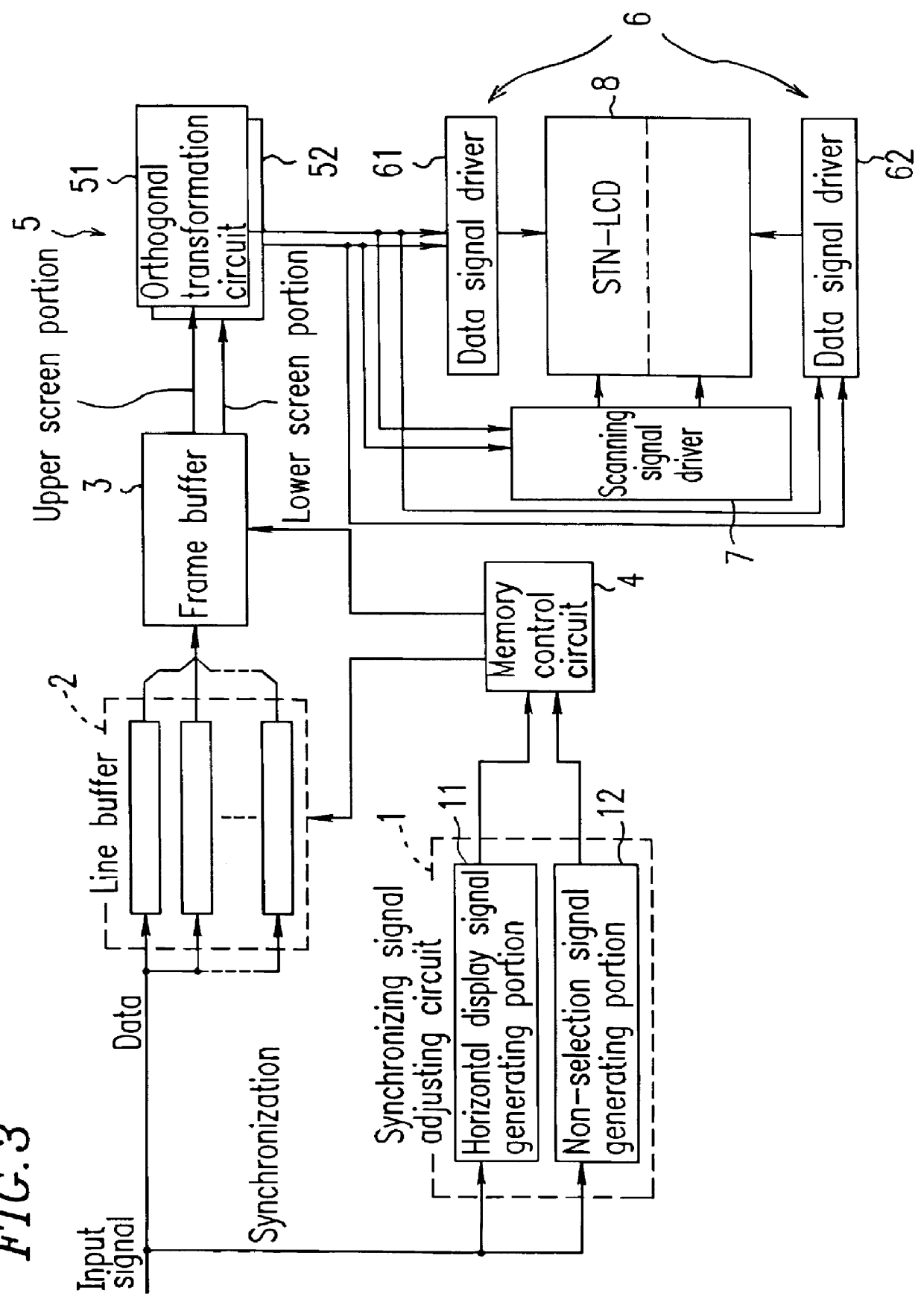
FIG. 3 is a block diagram of a driving circuit of an example according to the present invention. In this driving circuit, an intra-block dispersion driving method (Japanese Laid-open Publication No. 8-146382) using up-and-down division driving in which the number of scanning lines to be simultaneously selected is 4 and the number of block lines is 150 is applied to a high-speed response STN-LCD having a resolution of 800 H (dots / RGB).times.600 V (lines).

The driving circuit of the present example will be described in more detail, although having been described above.

The driving circuit of the present example includes a synchronizing signal adjusting circuit 1. The synchronizing signal adjusting circuit 1 includes a horizontal display signal generating portion 11 and a non-selection signal generating portion 12. The horizontal display signal generating portion 11 generates a horizontal display period signal over one frame period from an input synchronizing signal. The non-selection si...


PUM


Abstract

A driving circuit for a simple matrix type display apparatus in which an input data signal is stored in a frame buffer and subjected to orthogonal transformation, whereby a display is performed, includes: a plurality of line buffers whose number is equal to the number of scanning lines to be selected in accordance with a multiple-scanning line simultaneous selection method, respectively having a region I and a region II, wherein while one of the regions I and II is used for writing, the other is used for reading; and a frame buffer which allows data from the plurality of line buffers to be written during a plurality of horizontal non-display periods and all of the selected scanning lines of data to be written at a time, wherein the number of the plurality of line buffers is equal to the number of the selected scanning lines.

Description

1. Field of the InventionThe present invention relates to a driving circuit for a simple matrix type display apparatus in which an input data signal is subjected to orthogonal transformation with an orthogonal function, and the transformed signal is subjected to reverse transformation for display on a side of a simple matrix type display apparatus.2. Description of the Related ArtConventionally, simple matrix type liquid crystal display apparatuses typified by Super Twisted Nematic (STN) liquid crystal display apparatuses are known.This type of liquid crystal display apparatus has a structure in which a liquid crystal layer is interposed between two opposing glass substrates, and stripe-shaped scanning electrodes and data electrodes are disposed in a matrix so as to cross each other on the liquid crystal layer side of the glass substrate. In such a liquid crystal display apparatus, a voltage is applied to the scanning electrodes and the data electrodes, whereby liquid crystal at eac...

Claims


Application Information

Patent Timeline
IPC IPC(8): G09G3/36G09G5/36G09G5/393G02F1/133
CPCG09G3/3625G09G5/393
Inventor FURUKAWA, HIROYUKI
Owner SHARP KK
Why Eureka
Try Eureka