Electrochemical detector integrated on microfabricated capilliary electrophoresis chips

a microfabricated planar glass chip and electrochemical detector technology, applied in the direction of material electrochemical variables, instruments, separation processes, etc., can solve the problems of difficult detection of desired signals, difficult placement of detection electrodes within the high voltage region of separation columns, and difficult structure to manufacture and align, etc., to achieve accurate and convenient placement, reduce the interference effect of applied electrophoresis fields, and produce accurate results

Inactive Publication Date: 2000-04-04
RGT UNIV OF CALIFORNIA
View PDF9 Cites 162 Cited by
  • Summary
  • Abstract
  • Description
  • Claims
  • Application Information

AI Technical Summary

Benefits of technology

It is another object of the present invention to provide a microfabricated capillary electrophoresis chip with a microelectrochemical detector that minimizes the effect of interference from applied electrophoresis fields.
It is another object of the present invention to provide detector electrodes which are reproducibly, accurately and conveniently placed, robust and sensitive.
It is a further object of the present invention to provide detector electrodes which are precisely and stably positioned at the very end of the capillary where they are close to ground potential and thereby immune to pick up from the high electrophoresis potentials.
It is a further object of the present invention to provide a microfabricated capillary electrophoresis chip with integrated thin film electrochemical detector electrodes and electrophoresis electrodes which can be produced accurately and at low cost.

Problems solved by technology

This structure is very difficult to manufacture and align, and the placement of the detection electrodes within the high voltage region of the separation column is problematic.
The mechanical instability and poor definition of the electrode alignment can lead to significant electrical pickup or fluctuation in the background, making the desired signal very difficult to detect.
The presence of high voltage gradients and significant electrophoretic currents in the column near the electrodes can induce stray signals.
This is very difficult to do with conventional manufacturing techniques.
Any error in the placement will cause loss of analyte signal if the electrodes are too far from the opening or high voltage pick up if the electrodes are placed within the separation column.
Furthermore, fluctuations in electrode placement or electrode-electrode gap can cause severe fluctuations in the background signal producing noise.
Furthermore, the engineering of the electrical isolation by connection of the separation and detection capillary tubes with a grounded porous glass tube in the off-column format is rather difficult to assemble and operate, and the junction can be mechanically unstable and poorly defined.
In one case, although Slater and Watt (Slater, J. M.; Watt, E. J., On-chip Microbond Array Electrochemical Detector for use in Capillary Electrophoresis Analyst, 1994, 119, 2303-2307) photolithographically fabricated electrodes on a substrate, because they did not make a fully integrated separation and detection device, they were forced to use said undesirable junctions to couple their detector to a conventional cylindrical capillary.

Method used


Image

  • Electrochemical detector integrated on microfabricated capilliary electrophoresis chips
  • Electrochemical detector integrated on microfabricated capilliary electrophoresis chips
  • Electrochemical detector integrated on microfabricated capilliary electrophoresis chips

Examples


Embodiment Construction

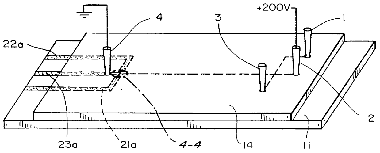
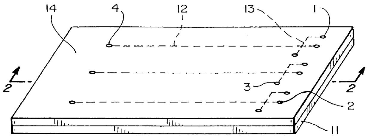
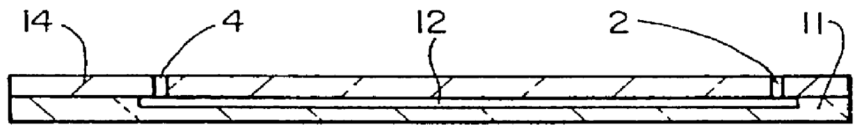
FIGS. 1 and 2 show a microfabricated capillary electrophoresis (CE) chip formed in accordance with the prior art. The capillary channels are formed on an etched glass substrate 11 by photolithography and chemical etching. The process is described by Woolley et al., Ultra-High-Speed DNA Fragment Separations Using Microfabricated Capillary Array Electrophoresis Chips, Proc. Nat'l. Acad. Sci., USA, 91, 11348-11352 (1994). The separation channel 12 and the injection channel 13 for injecting sample into the channel by stack or plug injection are described in the above reference. In one example, all channels were etched to a depth of 8 .mu.m; the separation channels were 100 .mu.m wide, and the injection channels were 50 .mu.m wide. The separation channels were 46 mm long, with a distance of 39 mm from the point of injection to the electrochemical detector. The injection channels were 22 mm long with a distance of 12 mm from the point of sample introduction to the injection region. A top ...


PUM

PropertyMeasurementUnit
depthaaaaaaaaaa
distanceaaaaaaaaaa
distanceaaaaaaaaaa

Abstract

A microfabricated capillary electrophoresis chip which includes an integral thin film electrochemical detector for detecting molecules separated in the capillary.

Description

This invention relates generally to an electrochemical detector as a component of an integrated separation and detection module on a microfabricated capillary electrophoresis chip and to a method of fabricating the electrochemical detector and more particularly to the design of a thin film electrochemical detector which can be precisely positioned in a microfabricated capillary.Electrochemical detection has been employed in liquid chromatography and in capillary electrophoresis (CE). It has been demonstrated that electrochemical detection is very sensitive and can measure 10.sup.-16 to 10.sup.-19 moles of sample with typical detection volumes from nL to pL (Ewing, A. G.; Mesaros, J. M.; Gavin, P. F., Electrochemical Detection in Microcolumn Separations, Anal. Chem., 66, 527A-536A, (1994); Voegel, P. D.; Baldwin, R. P., Electrochemical Detection with Copper Electrodes in Liquid Chromatography and Capillary Electrophoresis, American Laboratory, 28(2), 39-45, (1996)). Electrochemical m...

Claims


Application Information

Patent Timeline
Patent Type & Authority Patents(United States)
IPC IPC(8): G01N27/447G01N30/00G01N30/60G01N37/00
CPCG01N27/4473G01N27/44791G01N30/6095G01N27/447
Inventor MATHIES, RICHARD A.GLAZER, ALEXANDER N.WOOLLEY, ADAM T.LAO, KAIGIN
Owner RGT UNIV OF CALIFORNIA
Why Eureka
Try Eureka