Wide angle image-displaying sheet and system

Inactive Publication Date: 2000-04-11
3M INNOVATIVE PROPERTIES CO
View PDF16 Cites 55 Cited by
  • Summary
  • Abstract
  • Description
  • Claims
  • Application Information

AI Technical Summary

Benefits of technology

Also disclosed is an image-displaying system comprising the image-displaying sheeting discussed above, and a stationary light source disposed to improve the visibility of the image.

Problems solved by technology

Thus, in order to realize good visibility of the image, the range of possible entrance angles of the light source tends to be limited.
This makes it difficult to assemble a sign-displaying system so that a light source is placed near the edge of a sign surface (imaging surface) of a road sign for illuminating the sign.
However, it is difficult to form an image with good visibility on the uneven front surface for forming image-displaying sheets.
Although the areas other than the image area could be seen at a higher luminance than the image area for light incident at a relatively low entrance angle, it is difficult to increase the visibility of the image area since it only reflects diffusely.
However, due to limitations of both types of sheeting at high entrance angles, the luminance cannot be increased in the

Method used


Image

  • Wide angle image-displaying sheet and system
  • Wide angle image-displaying sheet and system
  • Wide angle image-displaying sheet and system

Examples


example 1

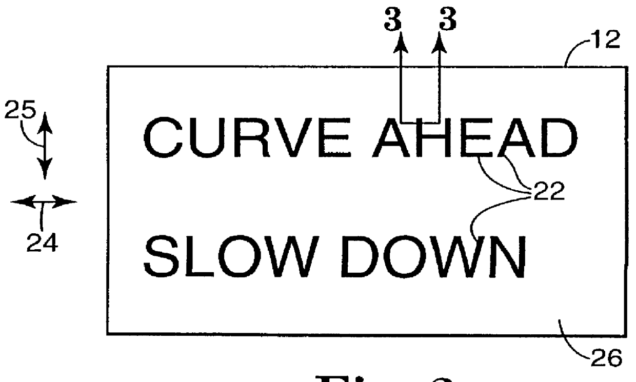
The prismatic sheeting was cut to obtain indicia in the form of Japanese language characters for "Curve Ahead, Slow Down". An adhesive was prepared by coating a composition of 99.375 wt. parts of an adhesive polymer (isooctylacrylate-acrylic acid copolymer) and 0.625 wt. parts of a bisamide crosslinking agent on a silicone-treated release paper and drying the composition at about 80.degree. C. to form a continuous adhesive layer. A prismatic sheeting was laminated to the adhesive layer with the flat surface of the prismatic sheeting in contact with the adhesive, at a pressure of about 1.5 kg / cm.sup.2. This layered combination was cut to obtain indicia in the form of Japanese language characters for "Curve Ahead, Slow Down". The release paper was removed and the indicia were applied to the front surface of a retroreflective sheeting with prismatic axes of all the characters in parallel alignment.

An image-displaying system was assembled by combining the image-displaying sheeting and a...

example 2

An image-displaying sheeting was prepared in the same manner as that of Example 1 except that 0.500 wt. parts of a red fluorescent dye (LUMOGEN Red 300, available from BASF) was added to the adhesive composition. The sheeting was observed in the same fashion as that of Example 1. The visibility of the image was rated "good". In particular, at entrance angles of about 70.degree. or higher, the retroreflective luminance of the characters was higher than that of the background portions, and the characters were sharply read. In addition, the visibility of the image was also good in the daytime and at twilight, since the adhesive contained the fluorescent dye.

example 3

An image-displaying sheeting was prepared in the same manner as Example 1 except that a different type of retroreflective sheeting was used. Upon inspection in the manner discussed above, the visibility of the image was rated "good". At entrance angles of about 70.degree. or higher, the retroreflective luminance of the characters was higher than that of the background portions, and the characters were sharply read.


PUM


Abstract

An imaging element is disposed on a front surface of a retroreflective sheeting to form an image-displaying sheeting. The imaging element includes a light-transmitting prismatic sheeting that has a surface provided with a plurality of parallel prisms. The imaging element also includes an adhesive layer that adheres the prismatic sheeting to the front surface of the retroreflective sheeting. At least a portion of the imaging element is shaped in the form of indicia. In some cases the prismatic sheeting itself is shaped in the form of indicia. In other cases the imaging element includes a light-transmitting colored layer disposed on the front surface of the retroreflective sheeting and shaped in the form of indicia. In the latter case, the prismatic sheeting can be shaped as before to match the indicia-shaped colored layer, or it can extend continuously across the entire retroreflective sheeting. A stationary light source can be added and suitably positioned to enhance visibility of the image in a viewing plane.

Description

The present invention relates generally to sheeting used for signs and the like to convey information in the form of indicia. More particularly, the invention relates to such sheeting that is retroreflective.The reader is directed to the glossary at the end of the specification for guidance on the meaning of certain terms used herein.It is known to use retroreflective sheeting having an image thereon for image-displaying members of road signs, billboards, and the like. The retroreflective sheeting is generally either of the beaded variety or of the cube corner variety. Beaded sheeting utilizes miniature beads composed of glass or other transparent materials in connection with a reflective coating. Cube corner sheeting utilizes a microreplicated structured surface having a multitude of miniature reflective faces arranged in sets of three approximately mutually perpendicular faces, each such set of three faces referred to as a cube corner element. Except for certain pavement marker ap...

Claims


Application Information

Patent Timeline
IPC IPC(8): G02B5/12G02B5/124G09F13/16G09F13/04
CPCG09F13/16G02B5/124
Inventor NAGAOKA, YOSHIYUKINAKAJIMA, TOSHITAKA
Owner 3M INNOVATIVE PROPERTIES CO
Why Eureka
Try Eureka