Lint roller assembly

a technology of lint rollers and parts, which is applied in the direction of cleaning equipment, manufacturing tools, portable power-driven tools, etc., can solve the problems of mechanical wear and tear of the rotating connection between mechanical failure, and the separate molding of the handle and the lint roller support, so as to achieve the effect of reducing the frictional conta

Inactive Publication Date: 2000-05-02
THE EVERCARE
View PDF7 Cites 94 Cited by
  • Summary
  • Abstract
  • Description
  • Claims
  • Application Information

AI Technical Summary

Benefits of technology

In order to minimize the frictional contact between the lint roller support and the adhesive lint roller, a plurality of circumferentially spaced and longitudinally extending ribs are formed along the outer periphery of the lint roller support. Since only the outer periphery of the ribs contact the i

Problems solved by technology

One disadvantage of this type of previously known lint roller assembly, however, is that the rotatable connection between the handle and lint roller support is subjected to mechanical wear and tear and, ultimately, mechanical failure.
A still further disadvantage of this type of previously known li

Method used


Image

  • Lint roller assembly
  • Lint roller assembly
  • Lint roller assembly

Examples


Embodiment Construction

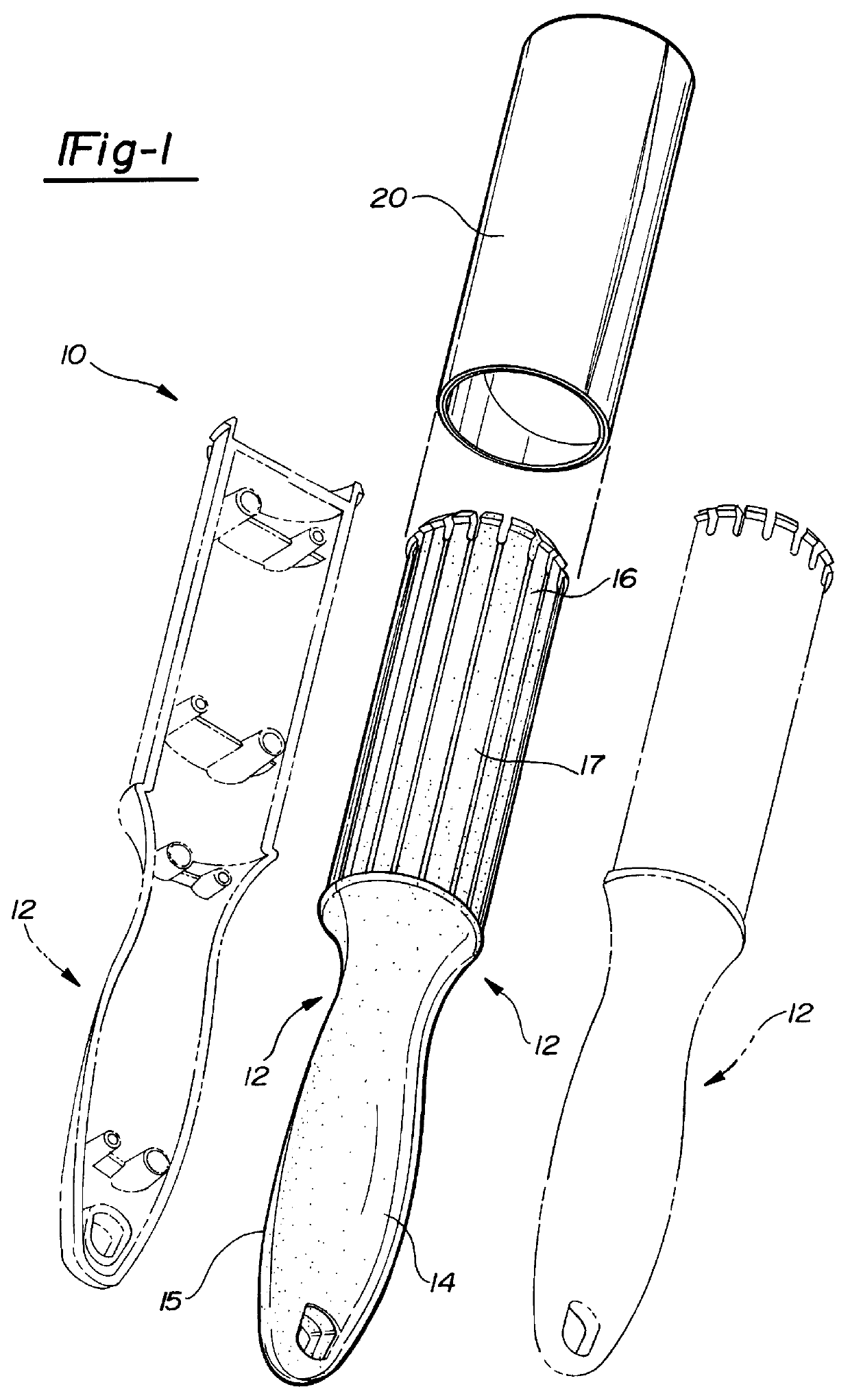
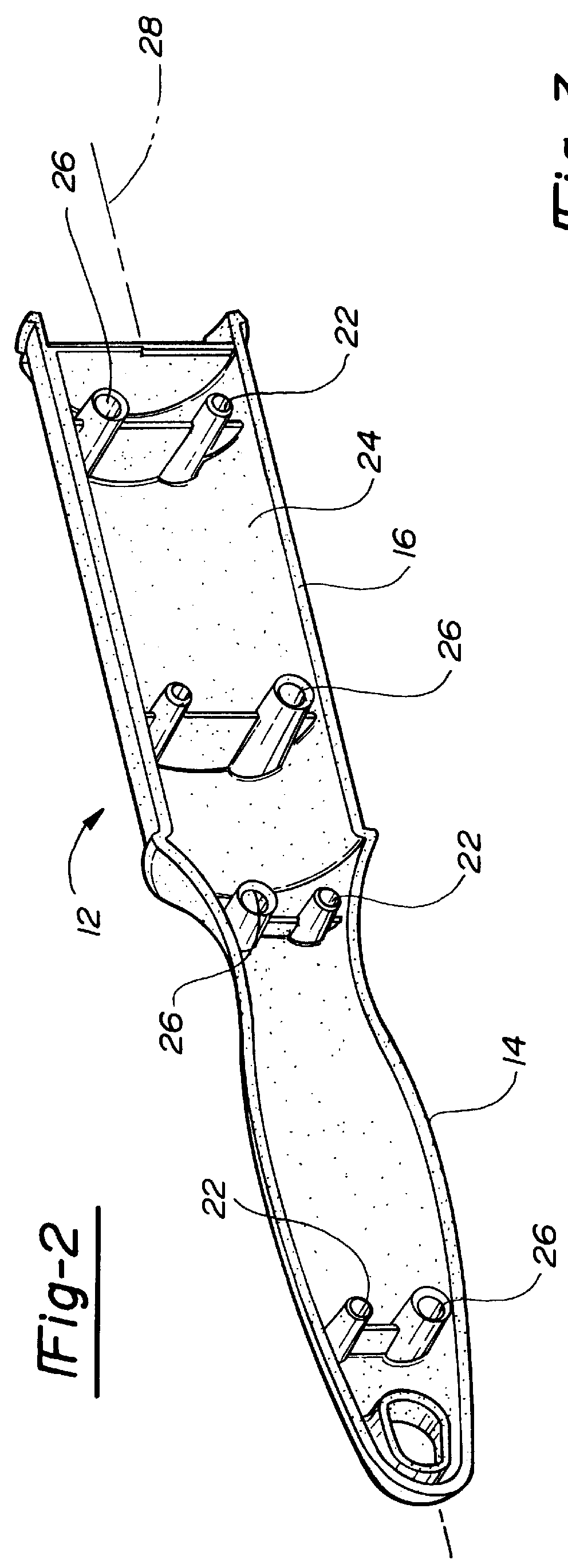
With reference first to FIG. 1, the preferred embodiment of the lint roller assembly 10 of the present invention is thereshown and comprises a pair of housing parts 12 which are substantially identical to each other. Each housing part 12, furthermore, includes an elongated handle section 14 and a longitudinally adjacent lint roller support section 16. The lint roller support section 16, furthermore, is generally semi-cylindrical in shape.

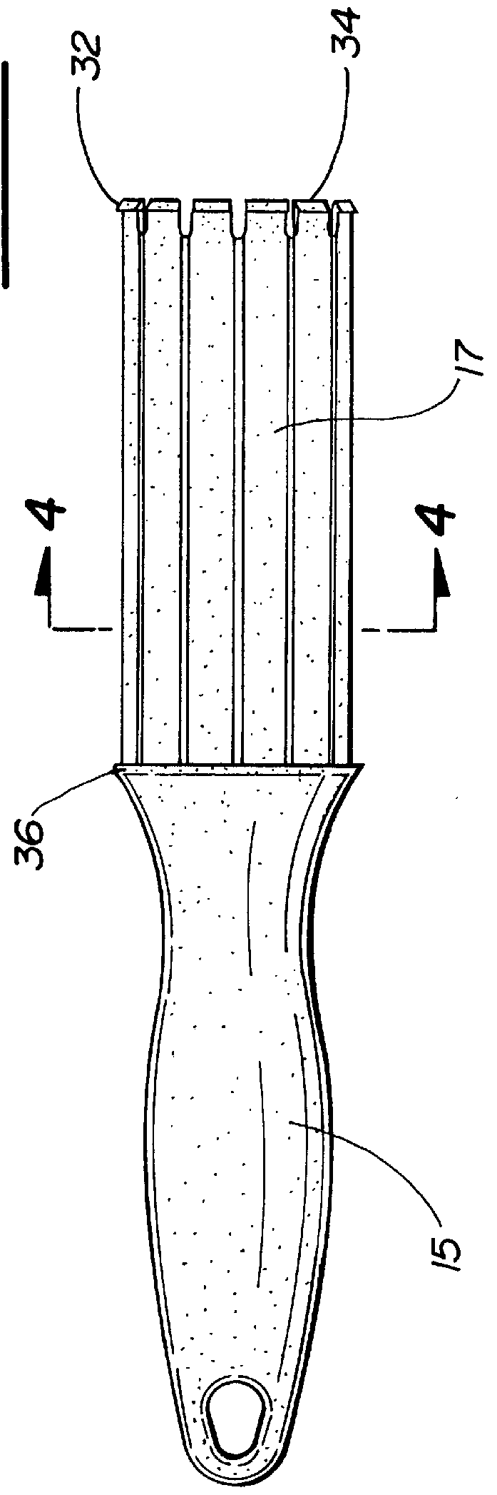
With the housing parts 1:2 secured together in facing relationship as illustrated in FIG. 1, the handle sections 14 abut together to form a handle 15 and, similarly, the semi-cylindrical lint roller support section 16 abut together to form a cylindrical lint roller support 17 having a predetermined outside diameter. A tubular and cylindrical adhesive lint roller 20 is then inserted over and rotatably supported by the lint roller support 17 in a fashion to be subsequently described in greater detail. However, the lint roller 20 has an inside diameter...


PUM


Abstract

A lint roller assembly is disclosed for rotatably supporting a tubular and cylindrical adhesive lint remover roller. The assembly includes a pair of elongated housing parts which are substantially identical to each other. Each housing part includes an elongated handle section and a semi-cylindrical lint roller support section longitudinally adjacent the handle section. The lint roller support section has an outer diameter less than the diameter of the adhesive roller. The housing parts are secured together in a facing relationship by registering pins and sockets formed on the housing parts. In doing so, the lint roller support sections form a cylindrical lint roller support for the adhesive roller while the handle sections abut against each other to form a handle.

Description

1. Field of the InventionThe present invention relates to a lint roller assembly.2. Description of the PriorThere are many previously known lint roller assemblies. These previously known lint roller assemblies typically comprise a handle secured to a cylindrical lint roller support. A tubular cylindrical adhesive lint roller is then removably mounted to the support such that the adhesive roller is rotatable relative to the handle. In use, the adhesive lint roller is rolled along a user's clothes to remove lint, hair and other debris.The previously known lint roller assemblies have used a number of different means to rotatably mount the lint roller support to the handle. For example, in U.S. Pat. No. 4,361,923 to McKay, the lint roller support and handle are separately constructed and then rotatably secured together. One disadvantage of this type of previously known lint roller assembly, however, is that the rotatable connection between the handle and lint roller support is subjected...

Claims


Application Information

Patent Timeline
IPC IPC(8): A47L25/00
CPCA47L25/005
Inventor MCKAY, JR., NICHOLAS D.
Owner THE EVERCARE
Why Eureka
Try Eureka