
Sample plate gripping mechanism

a technology of sample plate and grip, which is applied in the direction of manufacturing tools, instruments, separation processes, etc., can solve the problems of destroying the degree of repeatability and reliability, the gap between the sample plate and the member that makes contact, etc., and achieves reliable and repeatable manner, reliable transfer

Inactive Publication Date: 2008-03-04
THERMO FINNIGAN
View PDF6 Cites 7 Cited by
  • Summary
  • Abstract
  • Description
  • Claims
  • Application Information

AI Technical Summary

Benefits of technology

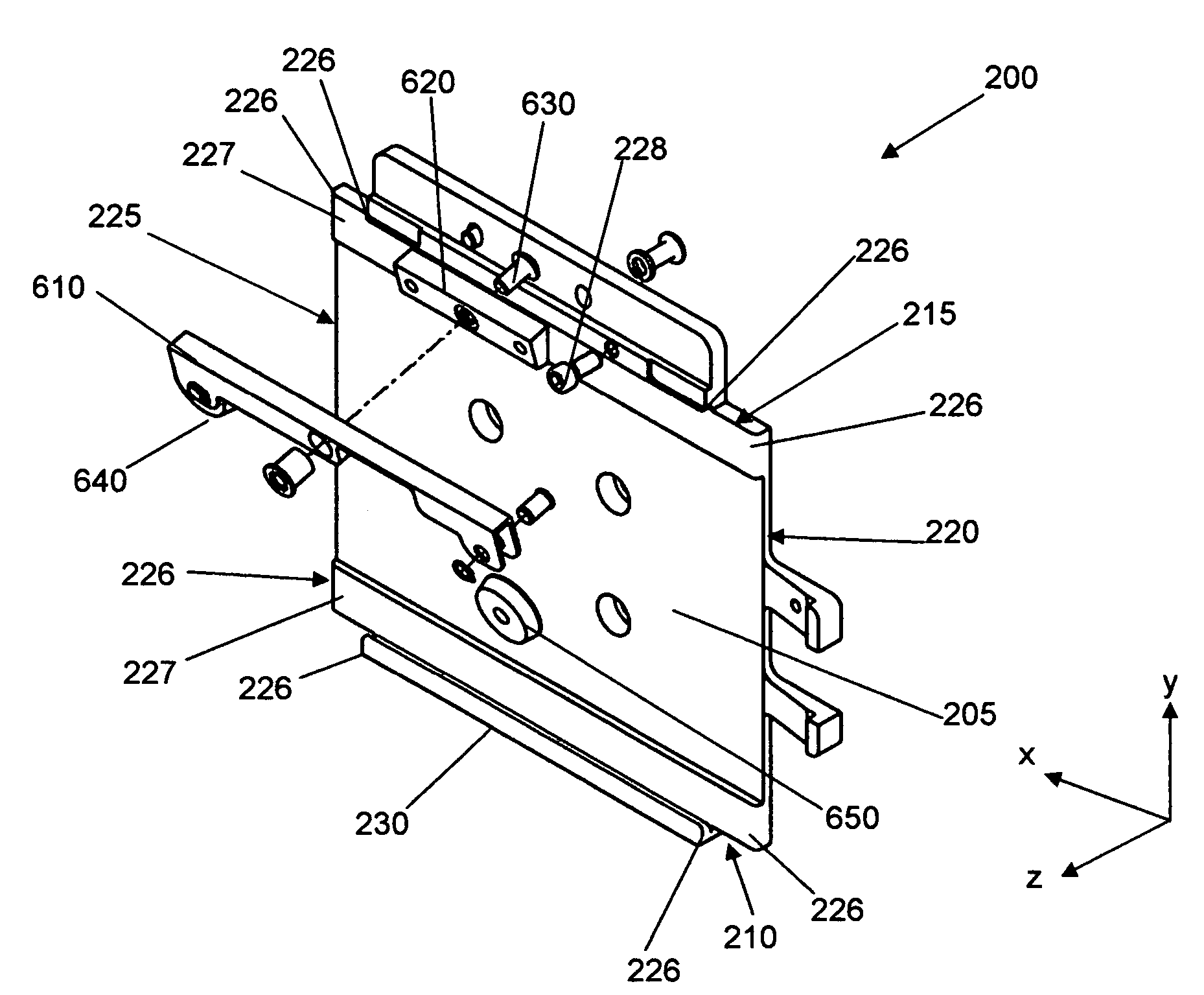
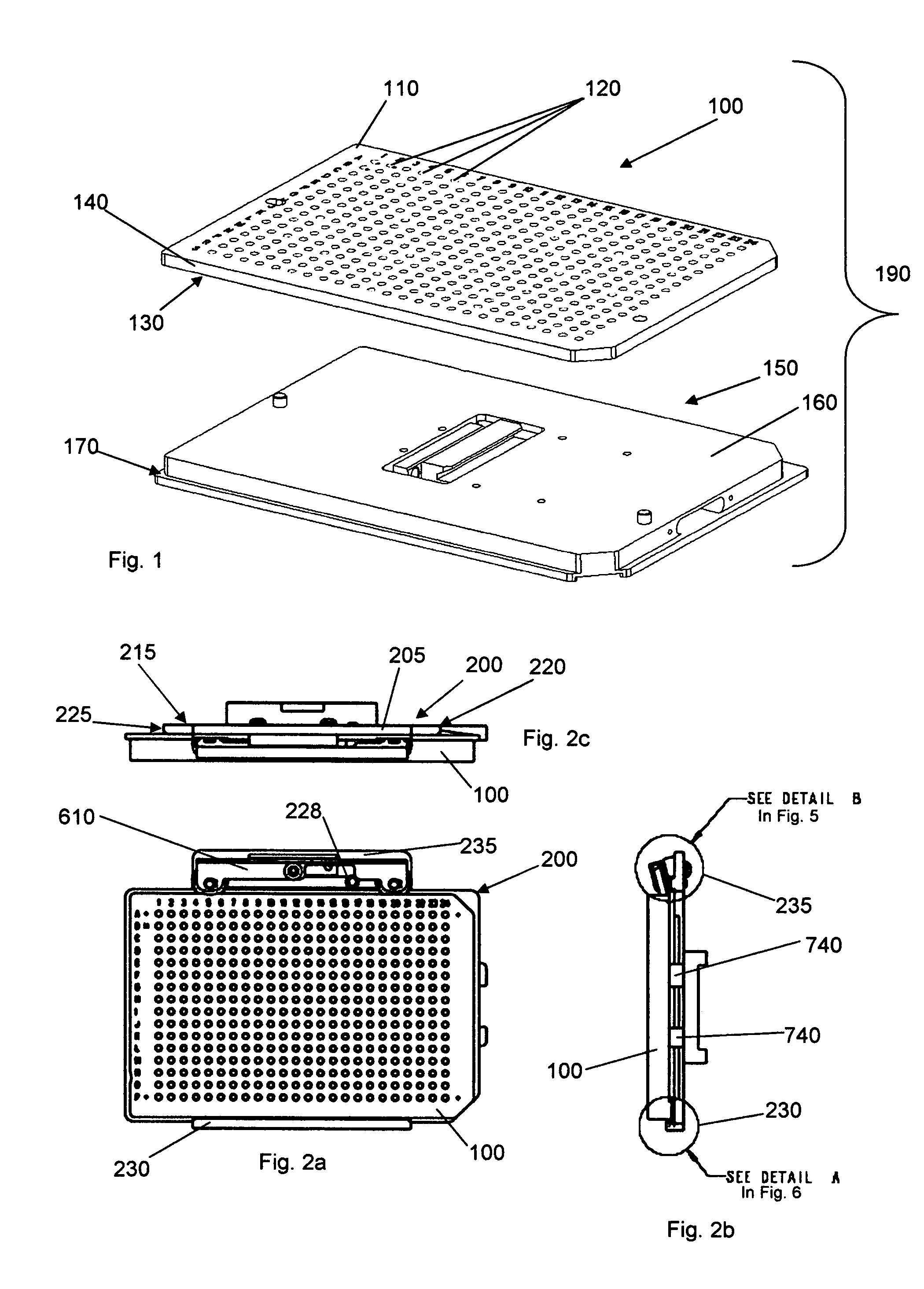
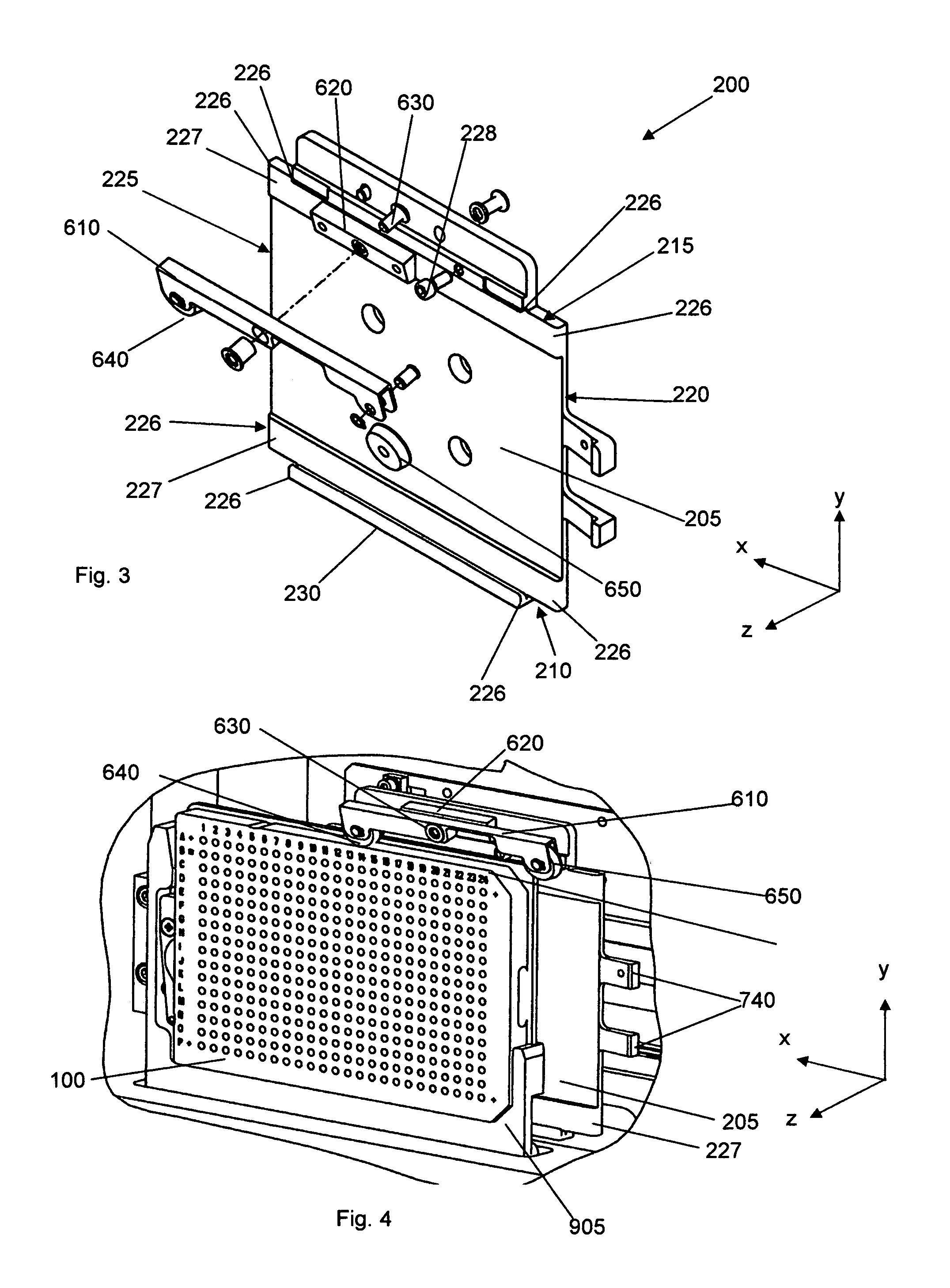
[0006]This invention provides novel methods and apparatus for releasably gripping MALDI sample plates so they can be analyzed by a mass analyzer. This invention enables reliable transfer of a typical rectangular, square or lipped structured sample plate, such as a microtitre plate by using only the sample plate features or the sample plate structure given. No additional aids must be attached to the sample plate in order to transfer or handoff. This invention also provides novel methods and apparatus for facilitating the transfer of a sample plate from one environment to another within a mass spectrometer system in a reliable and repeatable manner.
[0009]The apparatus can securely locate the sample plate in three translational coordinate axes. The apparatus can be operated to minimize frictional contact, prevent galling thus preventing the sample plate from locking and improving repeatablility. The apparatus can comprise a stop that limits the distance the sample plate can be guided into the apparatus.

Problems solved by technology

This frictional point contact made with a sample plate can cause galling of the sample plate and the member that makes contact with it.
Ultimately, this means that when a sample plate is transferred from one gripping means to another, the degree of repeatability and reliability can be destroyed.

Method used


Image

  • Sample plate gripping mechanism
  • Sample plate gripping mechanism
  • Sample plate gripping mechanism

Examples


Embodiment Construction

[0024]This invention is not limited to the particular embodiment described herein. There are a number of varied embodiments and these variations can be made by a person competent in the art and are therefore considered to be covered by the invention.

[0025]FIG. 1 illustrates a MALDI sample storage plate 100 and a sample plate adapter 150. The sample storage plate 100 is typically made of stainless steel or some other suitable material such as surgical grade stainless steel or silicon wafer, and has a top surface 110 having a plurality of target areas 120 on which sample spots are deposited, and bottom surface 130 opposite to the top surface 110. The bottom surface 130 of the sample storage plate 100 is designed to come into contact with the platform 160 of the sample plate adapter 150 to form the MALDI sample plate 190. The sample storage plate 100 has substantially parallel surfaces 110, 130 and a peripheral surface 140. The MALDI sample plate 190 is formed by releasably attaching t...


PUM


Abstract

An apparatus for releasably gripping a sample plate for use with a mass spectrometer has been developed, the sample plate having substantially parallel faces and a peripheral surface. The apparatus comprises a planar member and first and second guiding structures. The second guiding structure comprises a biasing mechanism which when activiated, provides a force that forces the second guiding structure towards the peripheral surface of the sample plate such that the sample plate is retained by the apparatus. Utilization of the configuration reduces frictional point contact thus reduces localized stress point resulting in yielding the surface material thus in effect guarding both sample plate and first guiding means from galling and / or reducing any type of material removal when gripping a sample plate, or releasing a sample plate.

Description

FIELD OF THE INVENTION[0001]The present invention generally relates to methods and apparatus for releasably gripping sample plates for use in mass spectrometry applications. This invention also relates to methods and apparatus for gripping mechanisms that enable transference of sample plates from one gripping mechanism to another.BACKGROUND OF THE INVENTION[0002]The Matrix Assisted Laser Desorption Ionization (MALDI) technique involves depositing a sample (analyte) and a matrix dissolved in a solvent as a spot on a sample plate. After the solvent has evaporated, the mixture of sample and matrix is left on the sample plate. Typically, the sample plate bearing the sample spot is inserted into an mass analyzer or into a sample source adjacent a mass analyzer. The mass analyzer is typically pumped out to provide a substantially vacuum environment before the sample at each spot is analyzed. The MALDI technique requires that a pulse from a laser irradiate the matrix and causes it to evapo...

Claims


Application Information

Patent Timeline
IPC IPC(8): B25J15/00H01J49/00
CPCB01L9/523G01N35/028B01L2300/0829G01N2035/042
Inventor ZANON, STEPHEN
Owner THERMO FINNIGAN
Learn More