Semiconductor circuit and power transistor protection circuit

a technology of shielding circuit and circuit, applied in the direction of electronic switching, pulse technique, instruments, etc., can solve the problems of large surge voltage, large power loss, and erroneous detection of overcurrent sta

Inactive Publication Date: 2000-05-02
MITSUBISHI ELECTRIC CORP
View PDF6 Cites 101 Cited by
  • Summary
  • Abstract
  • Description
  • Claims
  • Application Information

AI Technical Summary

Problems solved by technology

The value of the resistance is set to generate as small voltage as possible, since large voltage generated at the resistance causes large power loss.
The overcurrent protection circuit shown in FIG. 11 raises a new problem caused by the presence of the signal line 15P.
However, since the input signal is at the "L" level corresponding to the OFF signal level at this time, the overcurrent decision circuit 4P does not recognize the current flowing in the IGBT 1P to be overcurrent, and it therefore cannot signal a decision indicating the overcurrent state of the IGBT 1P, or an error output, to the outside.
The IGBT 1P is thus turned off at time T2 at which the main current is presenting a still larger current value, which inevitably causes a large surge voltage.
Moreover, in the reference (1), the problem that an overcurrent state is erroneously detected due to a noise and is externally outputted when the IGBT is OFF is left unsolved.
Accordingly, the references (1) to (3) do not provide means for solving this problem.
Therefore, if the overcurrent state occurs before the power transistor makes a transition from ON operation to OFF operation, the overcurrent state cannot be detected at the moment of its occurrence.
The current value flowing in the power transistor increases in this delay in the detecting timing, which causes the problem that the power transistor is controlled to the turned-off state in the condition or timing where the value of the main current has grown to a still larger current value over the overcurrent detection level (a reference level).
This problem may occur not only when the load includes only an inductance component of a load device such as a motor but also when the load includes resistance.
It can be said that this problem generally occurs when an overcurrent takes place in a switching circuit using a power transistor.

Method used


Image

  • Semiconductor circuit and power transistor protection circuit
  • Semiconductor circuit and power transistor protection circuit
  • Semiconductor circuit and power transistor protection circuit

Examples


first example

(First Example of Modification)

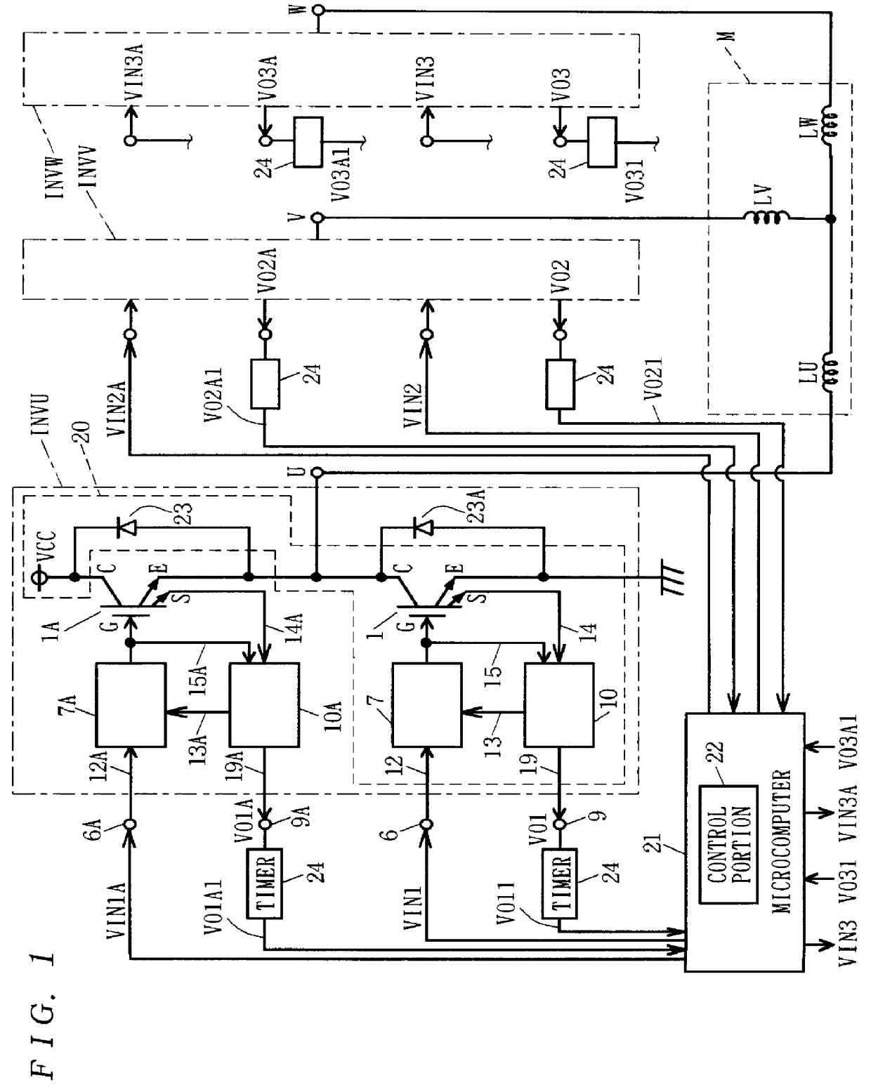
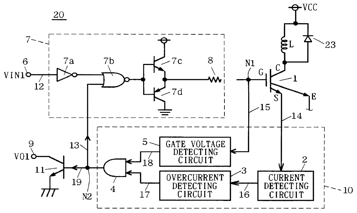
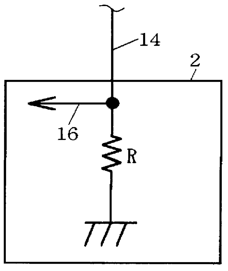
Although the IGBT 1 in the first preferred embodiment has the sense terminal S as shown in FIG. 1, FIG. 2 and FIG. 6, the power transistor in the semiconductor circuit according to the present invention is not limited to such a sense-equipped IGBT. For example, an overcurrent protection circuit for power transistor can be constructed similarly to that shown in FIG. 2 by using an IGBT having no sense terminal as the power transistor.

FIG. 9 shows an example thereof. FIG. 9 shows, for convenience, a modification of the first inverter circuit portion INVU shown in FIG. 1, but the structure of the circuit INVU1 shown in FIG. 9 can be applied also to the second and third inverter circuit portions INVV, INVW shown in FIG. 1 in the same way.

Needless to say, this modification provides the functions and effects described in the first preferred embodiment as well.

second example

(Second Example of Modification)

Although the load is the inductance L determined on the basis of the coils LU to LW of the motor M shown in FIG. 1 in the first preferred embodiment and the first example of modification, the load may be a resistance 25 as shown in FIG. 10, for example. When the load is the resistance 25, the main current flowing in the resistance 25 simply increases when the IGBT 1 is ON and no main current flows in the IGBT 1 when it is OFF. Accordingly, when the IGBT 1 becomes ON again, the main current does not cumulatively increase like in the case of the load of inductance. However, in this case, as well, an overcurrent may flow not only when the IGBT 1 is ON but also when it is making a transition from ON to OFF because of the effect of noise signal or variation in external voltage. Hence, applications of the semiconductor circuit of the present invention provide the same functions and effects as those described in the first preferred embodiment also when the l...

third example

(Third Example of Modification)

The power transistors are not limited to the IGBTs, but insulated-gate switching devices such as power MOSFETs can be used as the power transistors, for example.


PUM


Abstract

A decision circuit (10) monitors a main current flowing in an IGBT (1), and when operation of the IGBT (1) enters an overcurrent state and the control voltage applied to the control terminal (G) of the IGBT (1) is equal to or larger than the threshold voltage, it determines that the IGBT (1) is in the overcurrent state and places the IGBT (1) in an OFF state, and also outputs the result of the determination as an output signal to an external microcomputer from an error output terminal (9). Receiving this output signal, the microcomputer immediately fixes driving signals for the IGBT (1) and another IGBTs at an OFF signal level to disconnect these IGBTs, thus preventing the main current of the IGBT (1) from increasing to a still larger overcurrent to protect the IGBT (1). Generation of a turn-off surge voltage is suppressed in the overcurrent state by detecting the overcurrent state of the power transistor by earlier timing.

Description

1. Field of the InventionThe present invention relates to a circuit for detecting overcurrent state of main current flowing in a power transistor, and further to a semiconductor circuit for protecting the power transistor itself from the overcurrent on the basis of the detection of overcurrent state and also controlling driving of another power transistors. The technology of the present invention is applicable to an inverter circuit for a motor, for example.2. Description of the Background Art(Background Art 1)A conventional overcurrent protection circuit for an IGBT, one of the power transistors, will now be described referring to FIG. 11, and FIG. 2A to FIG. 12F.FIG. 11 is a block diagram showing an IGBT driving circuit device including a conventional IGBT overcurrent protection circuit. Note that the circuit shown in FIG. 11 relates to technical know-how or inside technology of the applicant of the present invention, which is publicly not known.In FIG. 11, the character 1P denote...

Claims


Application Information

Patent Timeline
Patent Type & Authority Patents(United States)
IPC IPC(8): H03K17/082H03K17/08
CPCH03K17/0828
Inventor IGARASHI, TAKASHI
Owner MITSUBISHI ELECTRIC CORP
Why Eureka
Try Eureka