In-drive correction of servo pattern errors

a technology of servo pattern errors and in-drive correction, which is applied in the direction of recording information storage, maintaining head carrier alignment, instruments, etc., can solve the problems of increasing the time each hda spends on the servo writer, increasing the time required for the use of the servo writer station, and therefore the cost associated with it. , to achieve the effect of improving the rro correction valu

Inactive Publication Date: 2000-05-09
MATSUSHITA KOTOBUKI ELECTRONICS IND LTD
View PDF12 Cites 90 Cited by
  • Summary
  • Abstract
  • Description
  • Claims
  • Application Information

AI Technical Summary

Benefits of technology

using said RRO correction table in the position calculations to iteratively improve the RRO correction values.

Problems solved by technology

However, one disadvantage arising from using the servo writer for this purpose is the time required for, and therefore the cost associated with, using the servo writer station.
These servo writers are relatively expensive in relation to other capital equipment needed to assemble and format disk drives.
However, this prior procedure increases the time each HDA spends on the servo writer, and additional servo writer time represents additional manufacturing costs for the HDA.
Most drive failures, if they are likely to occur, will occur during self-scan within one of these chambers, very early in the operational life of the drive.

Method used


Image

  • In-drive correction of servo pattern errors
  • In-drive correction of servo pattern errors

Examples


Embodiment Construction

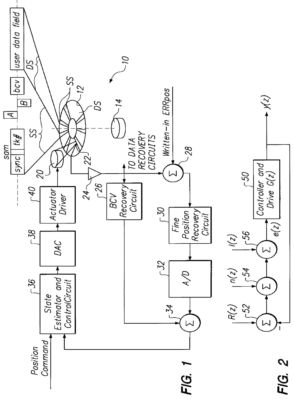
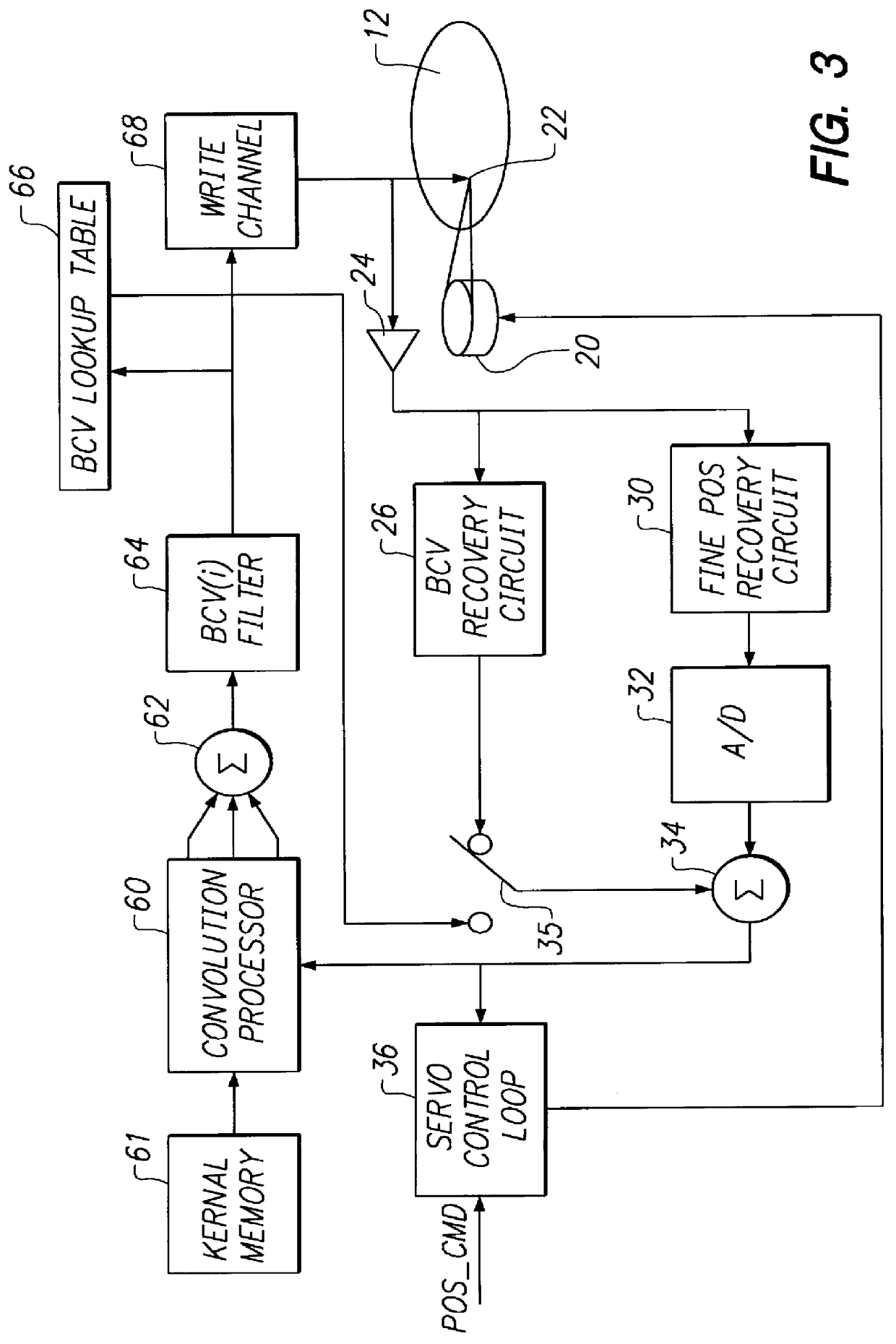
With reference to FIG. 1, a disk drive 10 includes a rotating data storage disk 12 which is rotated at a predetermined angular velocity by a speed-regulated disk spindle motor 14. The disk 12 defines a multiplicity of concentric data track locations. Each data track includes a sequence of user data sectors DS interrupted by a series of embedded servo sectors SS as graphed in the enlarged track segment in FIG. 1. In the enlarged track segment, each servo sector is shown typically to include a sync field, a servo address mark field, a track number field, and fine-position-providing servo bursts (e.g. circumferentially staggered, radially offset bursts A and B) and one or more burst correction value (BCV) fields. The servo sector SS is followed by a user data field DS which may or may not include a user data field header and which may be interleaved for error correction code purposes and have error correction remainder bytes appended at the end of a sequence of user data, as is convent...


PUM

PropertyMeasurementUnit
rotational speedaaaaaaaaaa
harmonic frequenciesaaaaaaaaaa
harmonic frequencyaaaaaaaaaa

Abstract

Embedded servo sectors within a data track of a hard disk drive including a rotating data storage disk and a closed loop rotary actuator structure for positioning a data transducer head relative to the data track are written by a method including the steps of positioning the rotary actuator structure relative to the data track with a laser-interferometer-based servo writer and writing a pattern of circumferentially sequential, radially offset fine position bursts within each servo sector with the data transducer head, this step including writing-in undetermined position errors within each pattern being written, moving the disk drive to a self scan environment away from the servo writer, operating the rotary actuator structure in closed loop for following the data track by reference to the servo burst pattern, extracting the undetermined position error from each pattern thereby to iteratively determine written-in position errors, generating burst correction values from the determined written-in position errors, and writing the burst correction values to the data track for later use by the closed loop rotary actuator structure during following of the data track to remove the written-in position errors.

Description

The present invention relates to head positioner servo loops using servo patterns for positioning disk drive heads. More particularly, the present invention relates to a method providing one-time correction of written-in servo pattern errors within a disk drive, while servoing on those servo patterns, following the servo-writing operation.Modern high performance disk drives employ head positioner servo loops. The function of the head positioning servo system within the drive is two-fold: first, to position the read / write head over a data track with sufficient accuracy to enable reading and writing of that track without error; and, second, to position the write element with sufficient accuracy not to encroach upon adjacent tracks to prevent data erosion from those tracks during writing operations to the track being followed. In order to satisfy these requirements, the tracking system must be designed to reject disturbances. These disturbances include noise from sources such as spindl...

Claims


Application Information

Patent Timeline
Patent Type & Authority Patents(United States)
IPC IPC(8): G11B21/10G11B5/596
CPCG11B5/59627G11B5/59638G11B5/59655
Inventor SHEPHERD, STANLEY H.EHRLICH, RICHARD M.WISEMAN, JAMES V.CURRAN, RICHARD T.AKIN, JR., WILLIAM R.
Owner MATSUSHITA KOTOBUKI ELECTRONICS IND LTD
Why Eureka
Try Eureka