Battery capacity measuring device

a battery capacity and measuring device technology, applied in the direction of noise figure or signal-to-noise ratio measurement, instruments, alarms, etc., can solve the problems of many batteries deviating, long calculation time, and not always corr

Inactive Publication Date: 2000-05-09
EMERSON NETWORK POWER ENERGY SYST NORTH AMERICA
View PDF7 Cites 43 Cited by
  • Summary
  • Abstract
  • Description
  • Claims
  • Application Information

AI Technical Summary

Problems solved by technology

Unfortunately, the system is highly dependent on ideal discharge profiles, from which many batteries deviate.
The state of the art solutions for predicting the remaining discharge time of a battery requires much memory space and computer

Method used


Image

  • Battery capacity measuring device
  • Battery capacity measuring device
  • Battery capacity measuring device

Examples


Embodiment Construction

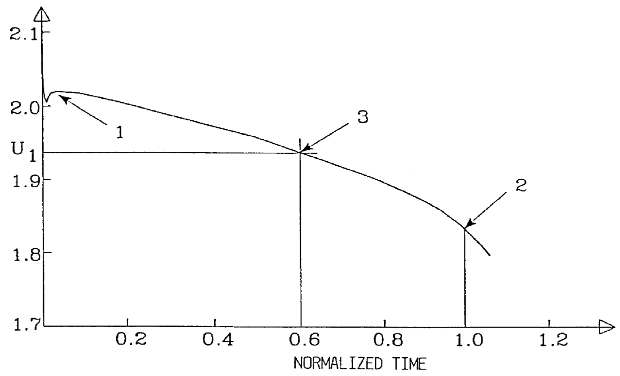
FIG. 1 shows a typical discharge curve for a battery cell having a nominal voltage of 2 V and is being discharged with a constant current. Just at the beginning of the discharge, the voltage drops very fast and then increases to a level called the plateau voltage 1. The time axis has been normalized according to the point in time when the voltage has dropped to a predetermined value, a so called final voltage 2. From this curve the extent of the remaining discharge time of the battery may be obtained by measuring a voltage U.sub.l and then finding the point on the time axis 3 in which the curve has the same value. In this example the value 0.6 is obtained, which means that 40% of the total discharge time remains.

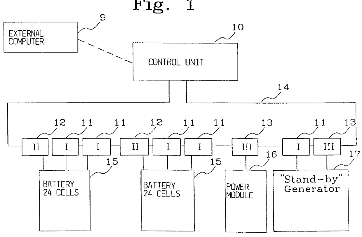
FIG. 2 is a schematic drawing of a battery system comprising a control unit 10, which gathers information and controls the supervision of the battery system via a number of supervision modules of different kinds 11-13. The control unit, which is able to communicate with an e...


PUM


Abstract

PCT No. PCT/SE97/00723 Sec. 371 Date Dec. 29, 1997 Sec. 102(e) Date Dec. 29, 1997 PCT Filed Apr. 29, 1997 PCT Pub. No. WO97/41448 PCT Pub. Date Nov. 6, 1997The present invention provides a fast, simple and accurate method for determining remaining battery capacity by taking into account the measured discharge parameters, such as voltage and current, which determine the shape of discharge curves for several different discharge currents. By normalizing the measured values, a normalized table is created that is used as a starting point for retrieving the remaining capacity in a battery at an arbitrary discharge current.

Description

The present invention relates to a method and a device to predict the resulting capacity of a battery.STATE OF THE ARTThe possibility to estimate the remaining energy content in a battery being discharged, is desirable, as the information may be used to determine the remaining operational time of the battery before it must be recharged or replaced.There are several different ways of achieving this, and in the patent specification EP 0420530 the estimate of the time for the discharge of the battery is based on a discharge curve being divided into one linear and one exponential part, and on a measured plateau voltage. This, combined with a real time supervision of the dynamic variables of the battery enables a continuously improved estimate of the remaining discharge time of the battery to be made. Unfortunately, the system is highly dependent on ideal discharge profiles, from which many batteries deviate.Another method of operation, according to WO 91 / 08494 is a system that supervise...

Claims


Application Information

Patent Timeline
IPC IPC(8): G01R31/36
CPCG01R31/3624G01R31/3658G01R31/3648G01R31/3842G01R31/396
Inventor WISTRAND, PER
Owner EMERSON NETWORK POWER ENERGY SYST NORTH AMERICA
Why Eureka
Try Eureka