

Artificially patinated copper material
a technology of artificial patina and copper, which is applied in the field of artificial patina of copper material, can solve the problems of affecting the possibility that a part of the artificial patina will peel off or fall off in a relatively short time, and the long time it takes to produce a natural patina, etc., to achieve the effect of promoting natural patina growth, not affecting or impairing the appearance or aesthetics, and excellent formability
- Summary
- Abstract
- Description
- Claims
- Application Information
AI Technical Summary
Benefits of technology
Problems solved by technology
Method used
Image

Examples
first embodiment
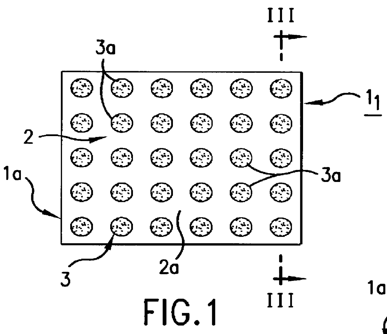
In a first embodiment, an artificially patinated plate 1 (the first copper plate 1.sub.1) as shown in FIGS. 1 and 3 was obtained by the following procedure.
A rectangular copper base plate 1a 0.35 mm in thickness, 365 mm in width, and 1212 mm in length was first polished on the surface, then cleaned with a 5% dilute sulfuric acid, rinsed, and dried. The surface of this copper base plate 1a was treated with a sulfiding solution to form a copper sulfide layer 2 thereon. The sulfiding solution used was one made up of 100 liters of water, 12 kg of sodium sulfide, and 1 kg of sodium silicate. A copper sulfide layer 2 with a uniform thickness of about 0.3 .mu.m was formed on the whole surface of the copper base plate 1a. After being sulfided in this manner, the plate was neutralized with 5% sodium sulfate, followed by rinsing and drying.
Subsequently, a resin solution mixed with basic copper carbonate in particle form was sprayed on the surface of the copper sulfide layer 2, which was then ...
example 2
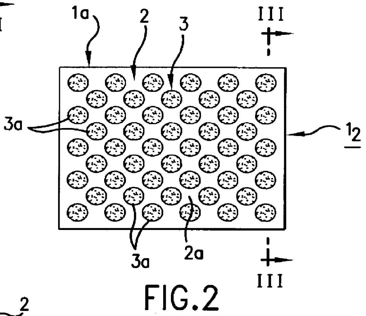
In a second embodiment, another artificially patinated plate 1 (the second copper plate 1.sub.2) as shown in FIGS. 2 and 3 was obtained under the same conditions as in Example 1, using however a spray solution of partly different quantities of the components and partly different spray conditions.
second embodiment
The sprayed solution in the made up of 16 kg of the aforementioned resin, 10.2 kg of basic copper carbonate, 0.5 kg of butyl cellosolve, 0.5 kg of DOP, and 3.7 kg of BTA water. The spraying condition were so set that the artificially patinated layer density was 80%. That is to say, the percentage of the exposed sulfide surface 2a was lower than that on the first copper plate 1.sub.1.
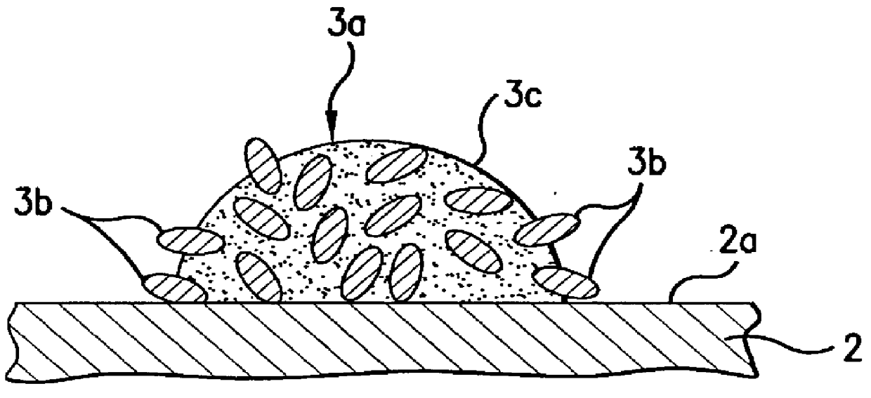
It is to be understood that FIG. 2 schematically shows the dispersed state of artificially patinated layer grains 3a. In the second copper plate 1.sub.2, too, artificially patinated layer grains 3a of various sizes and shapes are formed on the surface of the copper sulfide layer 2 in a randomly disperse pattern as in the first copper plate 1.sub.1 (FIG. 5). Also, as in the first copper plate 1.sub.1, each artificially patinated layer grain 3a is in the form of capsule with patina component copper carbonate enclosed in resin, but part of inorganic particles 3b of basic copper carbonate are exposed out of ...
PUM
| Property | Measurement | Unit |
|---|---|---|
| Fraction | aaaaa | aaaaa |
| Fraction | aaaaa | aaaaa |
| Fraction | aaaaa | aaaaa |
Abstract
Description
Claims
Application Information