Threading apparatus for sewing machine

a sewing machine and threading technology, applied in sewing machines, needle bars, textiles and paper, etc., can solve the problems of difficult threading operation, tremendous laborious elderly people, and manual threading in itsel

Inactive Publication Date: 2000-05-30
STEP Y K
View PDF5 Cites 8 Cited by
  • Summary
  • Abstract
  • Description
  • Claims
  • Application Information

AI Technical Summary

Problems solved by technology

Manual threading, in itself, is a laborious operation even for young people with good eyesight.
It is tremendously laborious for elderly people.
Poor lighting on needle eyes makes the threading operation tougher.
Needless to say, manual threading for an embroidering machine as shown in FIG. 7 requires more time and energy because many needles are involved.
However, the following technical problems exist.
As a result, incoming air weakens the air flow from the suction hole 4, and a yarn may not be properly guided into a small needle eye.
(2) A shallowly inserted needle does not provide

Method used


Image

  • Threading apparatus for sewing machine
  • Threading apparatus for sewing machine
  • Threading apparatus for sewing machine

Examples


Embodiment Construction

The following description focuses on an embodiment of a threading apparatus 100.

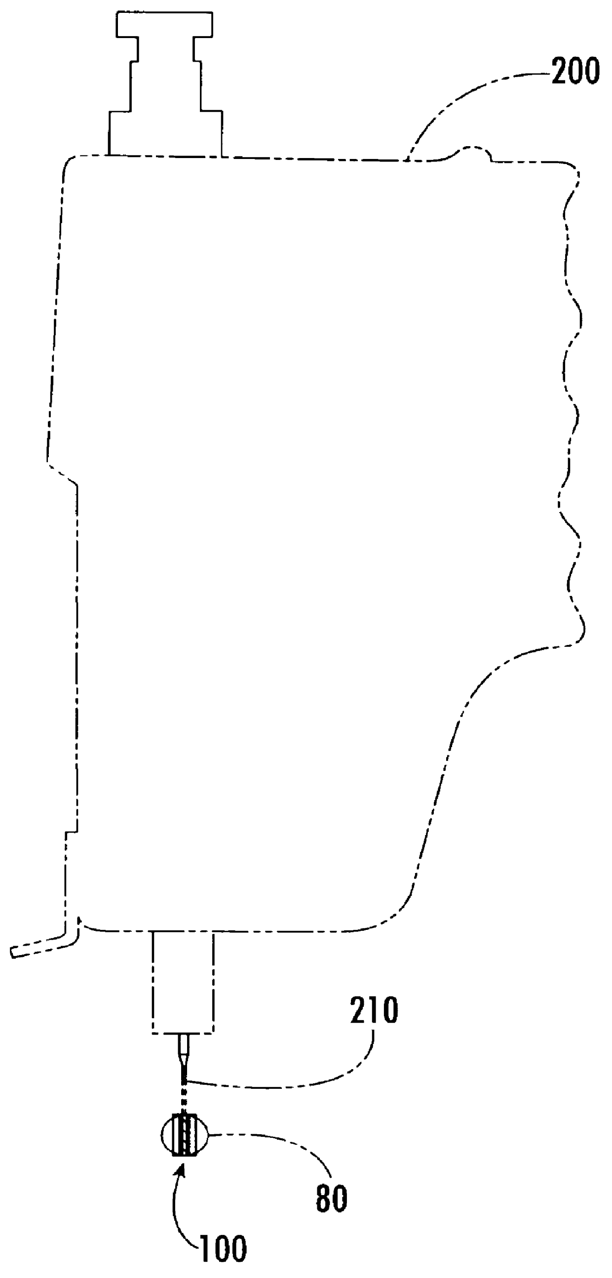
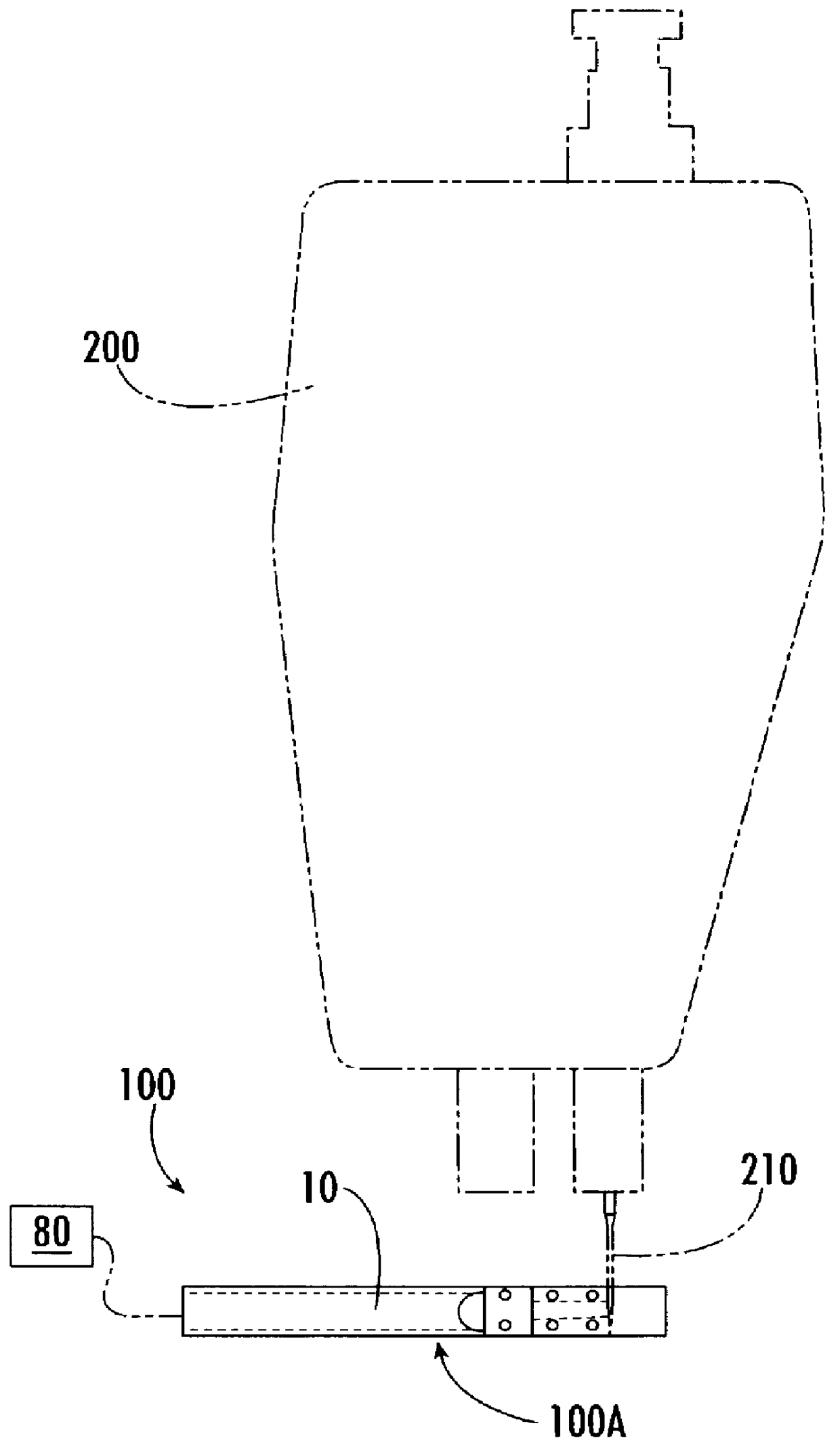
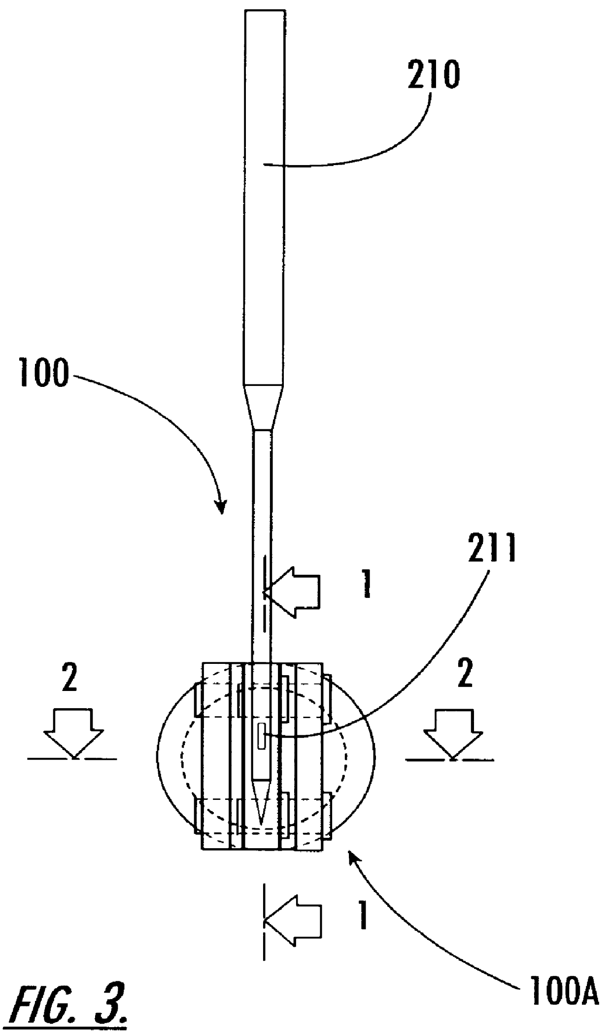
A threading apparatus 100 has an air suction device 100A for forming an air flow to be directed toward a needle eye 211 to guide a yarn through the eye 211. As illustrated in FIG. 9, the air suction device 100A is comprised of an external air device 80 generating reduced pressure, an air suction pipe 10 connected to the air device 80, and an air path 40 leading to the front portion of the air suction pipe 10. The air path 40 is comprised of a pair of leaf springs 20,20 which hold a needle, and upper and lower elastic members in parallel 31,32 positioned between the pair of leaf springs 20,20. The upper and lower elastic members 31,32 are connected to the front portion of the air suction pipe 10, and made to perform forward and backward movements by means of an air cylinder 70 as shown in FIGS. 8 and 9 to assist the threading operation. With the air cylinder 70, the air suction device 100A is mounted on a...


PUM


Abstract

The present invention provides an air suction device for a threading apparatus that creates an air flow to be directed toward a needle eye in order to guide a yarn through the eye. The air suction device is comprised of: (a) an air device externally provided for generating reduced pressure; (b) an air suction pipe connected to the external air device; and (c) an air path leading to a front portion of the air suction pipe. The air path is comprised of a pair of leaf springs to horizontally hold a needle, and upper and lower elastic members which run parallel between the pair of leaf springs. To effectively direct air into the needle eye, an air-tight environment is provided around the needle eye: (1) air entry above and beneath the needle eye is prevented by the body of the needle; (2) air entry from both sides of the needle is prevented by the pair of leaf springs that hold the needle; and (3) air inflow behind the needle is prevented by rear-positioned elastic members which tightly fit the needle.

Description

1. Field of the InventionThe present invention relates to a threading apparatus to be attached to a sewing machine or an embroidering machine to automatically guide a sewing yarn into a needle eye.2. Prior ArtManual threading, in itself, is a laborious operation even for young people with good eyesight. It is tremendously laborious for elderly people. Poor lighting on needle eyes makes the threading operation tougher. Needless to say, manual threading for an embroidering machine as shown in FIG. 7 requires more time and energy because many needles are involved.To ease threading operations, various attempts have been made. Japanese Patent Laid-Open Publication No.7-88276 (FIG. 10, prior art) discloses that a threading apparatus 1 is comprised of:(1) a needle insertion hole 3 provided vertically in the body 2;(2) a suction hole 4 intersecting with the needle insertion hole 3; and(3) a pipe 15 connected to the insertion hole 4 and a suction chamber 20 for threading a yarn into a needle...

Claims


Application Information

Patent Timeline
IPC IPC(8): D05B87/00D05B87/02
CPCD05B87/00D05D2207/04
Inventor UEMOTO, HARUYOSHI
Owner STEP Y K
Why Eureka
Try Eureka