Modular fluid flow system with integrated pump-purge

a fluid flow system and module technology, applied in the direction of valve housings, transportation and packaging, container discharging methods, etc., can solve the problems of increased corrosion or failure rate of connection, toxic or corrosive process gases, stress within the fluid transfer conduit or at the connection point of the conduit to the gas handling element,

Inactive Publication Date: 2000-05-30
APPLIED MATERIALS INC
View PDF4 Cites 93 Cited by
  • Summary
  • Abstract
  • Description
  • Claims
  • Application Information

AI Technical Summary

Problems solved by technology

In many instances the process gases are toxic or corrosive, or both.
The same problems that occur with the maintenance of gas handling systems are applicable to fluids in general, including hazardous liquids.
To avoid the formation of a closed tolerance loop, it is necessary that the pump-purge manifold or a portion of the modular / monolithic gas handling system manifold to which it is attached be sufficiently free floating to permit making of all necessary connections without creating stress within such connections which can lead to an increased rate of corrosion or failure of the connection.
If at least three of gas handling elements are present within the loop and these three elements are fixed in position relative to each other, the result is a closed-tolerance loop, i.e. there is a limited tolerance for the position of the plumbing relative to the gas handling elements and if this tolerance is exceeded, this results in stress within the fluid transfer conduit or at the connection point of the conduit to the gas handling element.
The VCR fittings are welded fittings, and each time one of these fittings has to be opened, there is considerable down time.
In addition, the welding creates a corrosion site at the heat affected zone on each side of the valve.
Each time an element of the gas handling system has to be changed out, there is a considerable amount of time required for replumbing of tubing and replacement of VCR fittings.
As a result, the maintenance work and down time for a hazardous gas stick 103 is extensive.

Method used


Image

  • Modular fluid flow system with integrated pump-purge
  • Modular fluid flow system with integrated pump-purge
  • Modular fluid flow system with integrated pump-purge

Examples


Embodiment Construction

of the Pump-Purge Apparatus

FIG. 6 illustrates the pump-purge valving system and manifold 600 which enables the integration of the critical pump-purge function into the gas handling sticks. FIG. 6 illustrates one preferred embodiment design and one skilled in the art may use the concepts taught here to design different flow paths than those shown in FIG. 6 to accomplish the same purpose.

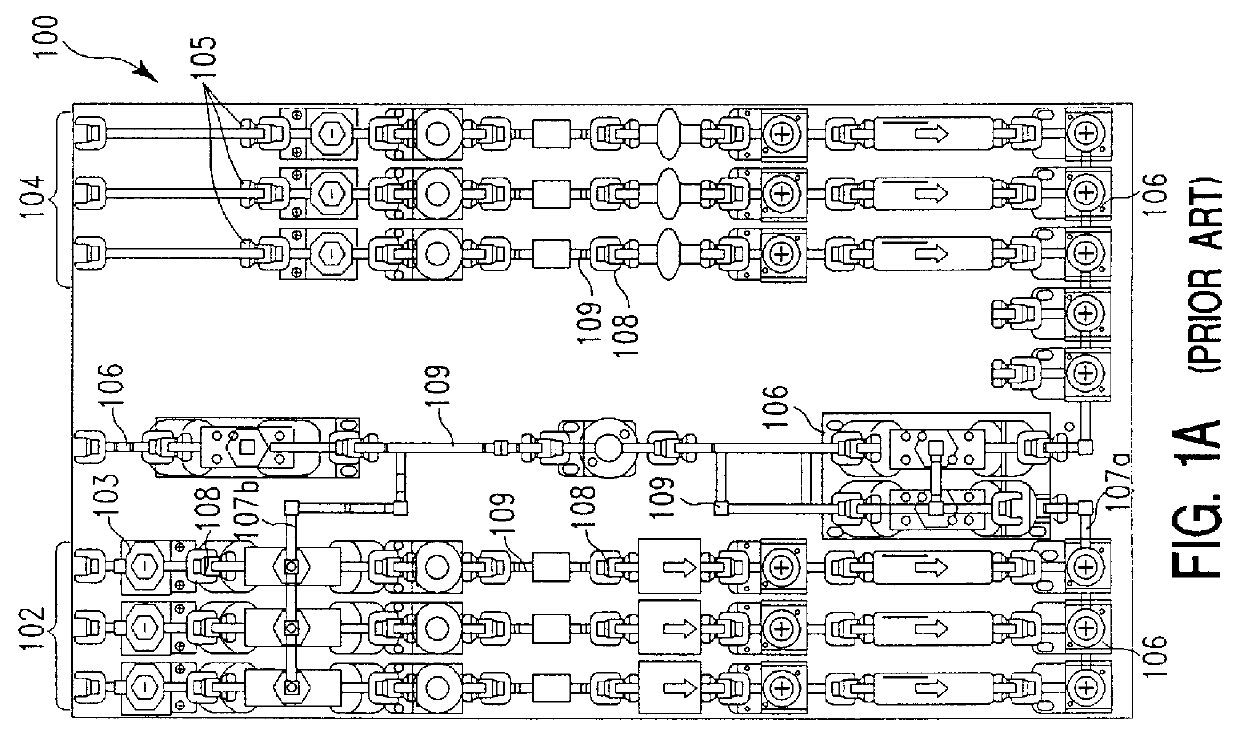
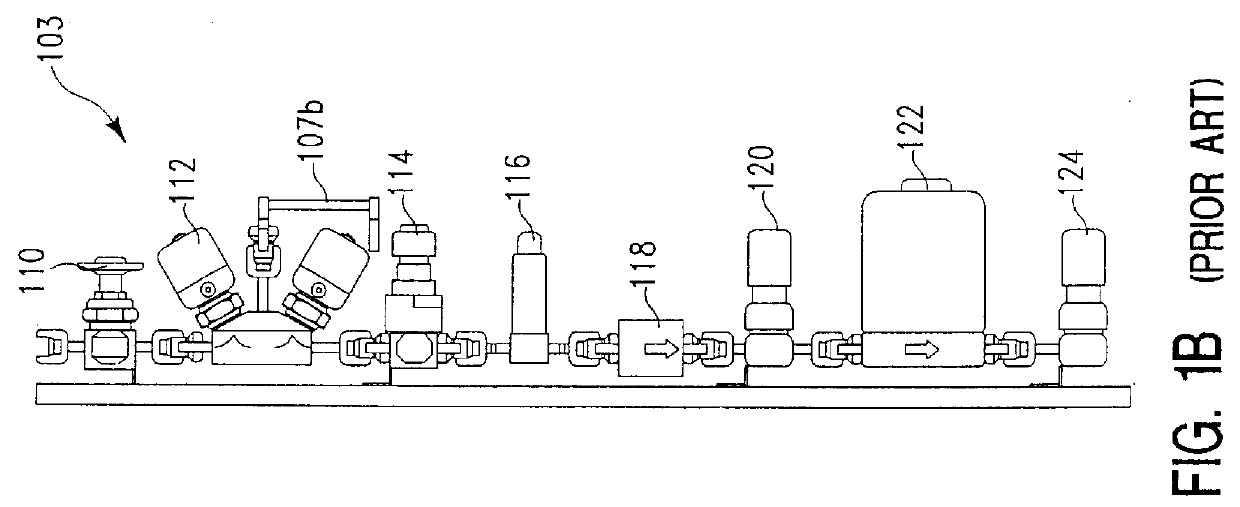
With reference to FIG. 1, in the past, the pump-purge system was mounted on the gas handling system pallet, but was connected to the individual hazardous gas handling sticks by plumbing conduits 107a and 107b. We have added pump-purge fluid transfer conduits to the monolithic manifolds which connect the elements of the hazardous gas handling stick. We have then designed a pump-purge manifold and valving system which can be attached as a module to one end of the gas handling sticks, to enable the pump-purge function within the entire bank of hazardous and non-hazardous gas handling sticks.

In particular...


PUM

PropertyMeasurementUnit
diameteraaaaaaaaaa
diameteraaaaaaaaaa
diameteraaaaaaaaaa

Abstract

This disclosure describes a modular, monolithic pump-purge system which can be integrated into a modular, monolithic fluid handling system without creating a closed tolerance loop. In particular, the pump-purge system comprises a plurality of valves mounted on a modular and monolithic manifold which can be attached to the modular, monolithic fluid handling system. At least a portion, and preferably all of the fluid transfer conduits necessary for either applying a vacuum (or other evacuation means) to a fluid handling system conduit which is to be evacuated (pumped), or for transfer of flushing fluid within a conduit (purging) are present within monolithic manifolds of the fluid handling system. The modular, monolithic manifold of the pump-purge system contains openings and fluid flow conduits which correspond with openings and fluid flow conduits of the modular, monolithic fluid handling system, to enable evacuation or flushing of a selected fluid flow conduit within the fluid handling system. To avoid the formation of a closed tolerance loop, it is necessary that the pump-purge manifold or a portion of the modular, monolithic fluid handling system manifold to which it is attached be sufficiently free-floating to permit making of all necessary connections without creating stress which can lead to an increased rate of corrosion or failure of the connection. In a preferred embodiment gas handling system, the gas handling flow lines which make up the system are comprised of individual sticks of gas handling elements, each of which is attached to the manifold of the pump-purge system so that it is free-floating.

Description

1. Field of the InventionThe present invention pertains to a new concept in fluid flow control systems such as gas flow control systems for use in semiconductor processing apparatus. Semiconductor processing utilizes inert, toxic, and corrosive gases which require the use of various flow control and filtering devices to ensure that the right quantity of contaminant-free gas reaches the semiconductor processing chamber. The control and filtering devices are assembled in clusters of elements which are typically mounted on a pallet for handling and maintenance purposes. The present disclosure makes possible the use of clusters of gas control and processing elements without the need for pipe fitting and plumbing activities which require special skill and which generate expensive down time. The general concepts involved are applicable to fluid flow systems in general.2. Brief Description of the Background ArtThere are numerous semiconductor processing steps which require the use of speci...

Claims


Application Information

Patent Timeline
Patent Type & Authority Patents(United States)
IPC IPC(8): F15B13/00F17C13/04H01L21/00C23C16/44F16K27/00F15B13/08F16K11/10
CPCC23C16/4408F15B13/0825F15B13/0828F15B13/0871F15B13/0892F15B13/0896F17C13/04H01L21/67017F15B13/0817F17C2270/0518F17C2205/0146F17C2205/0329F17C2205/0338F17C2205/0341F17C2205/0385F17C2221/014F17C2221/016F17C2227/044F17C2250/0636Y10T137/5109Y10T137/5283Y10T137/87885
Inventor MANOFSKY, JR., WILLIAM L.FITTRO, GARY CURTIS
Owner APPLIED MATERIALS INC
Why Eureka
Try Eureka