Driving method of liquid crystal display device

a technology of liquid crystal display and driving method, which is applied in the direction of instruments, computing, electric digital data processing, etc., can solve the problems of image inversion, inability to achieve a bend orientation state, and a decrease in contras

Inactive Publication Date: 2000-05-30
AU OPTRONICS CORP
View PDF15 Cites 140 Cited by
  • Summary
  • Abstract
  • Description
  • Claims
  • Application Information

AI Technical Summary

Benefits of technology

is to provide a driving method of a liquid crystal display device which forcibly returns an OCB cell to a bend orientation state in a short period when it has transformed from a bend orientation state to a splay orientation state during image display.

Problems solved by technology

Twisted nematic (TN) cells, which at present are widely used in TFT color liquid crystal display devices (TFT / LCDs), have a small view-field angle, which results in a problem that when an LCD panel surface is viewed from an oblique direction, the contrast decreases and image inversion occurs.
However, there occurred unsuccessful cases in which more than several tens of seconds took to attain a bend orientation state, or part of pixels are left untransferred to a bend orientation state.
Although this allows the liquid crystal display device to have a desired wide view-field angle characteristic, the image quality required for it cannot be obtained easily.
Further, the above measure is not practical.
There is another problem that even if transfer from splay orientation to bend orientation is effected at a start of operation, for a certain reason the OCB cell may return to a splay orientation state during the operation, in which case normal display is not performed unless the power is turned on again.
Therefore, certain period is needed to restore the bend orientation state, thus display cannot be turned on instantaneously.

Method used


Image

  • Driving method of liquid crystal display device
  • Driving method of liquid crystal display device
  • Driving method of liquid crystal display device

Examples


first embodiment

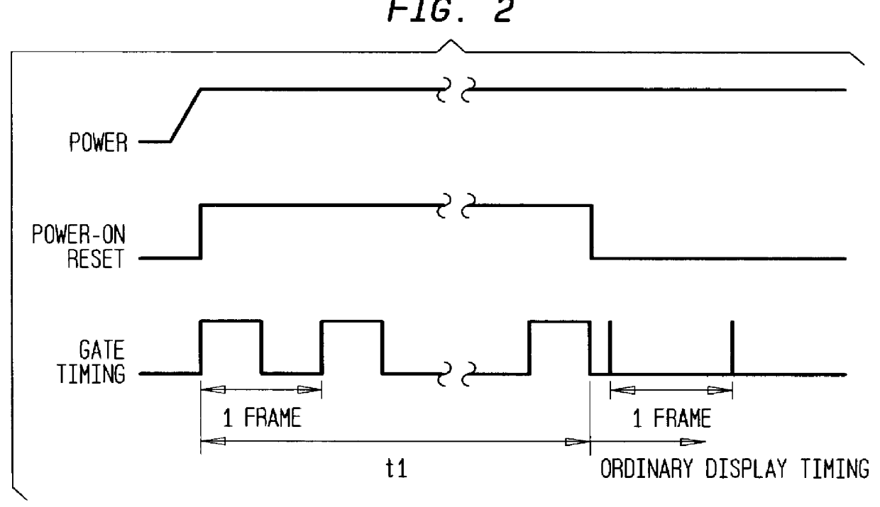
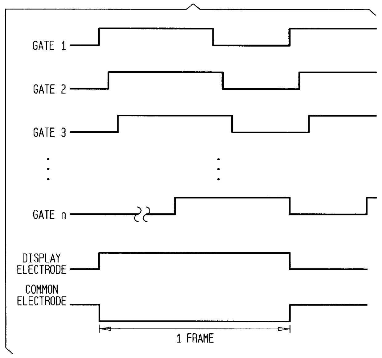
With reference to FIGS. 1-4, a description will be made of a liquid crystal display device, its driving method, and its driving device according to the subject invention in which an OCB cell is transferred from a splay orientation state to a bend orientation state at a start of operation of the liquid crystal display device.

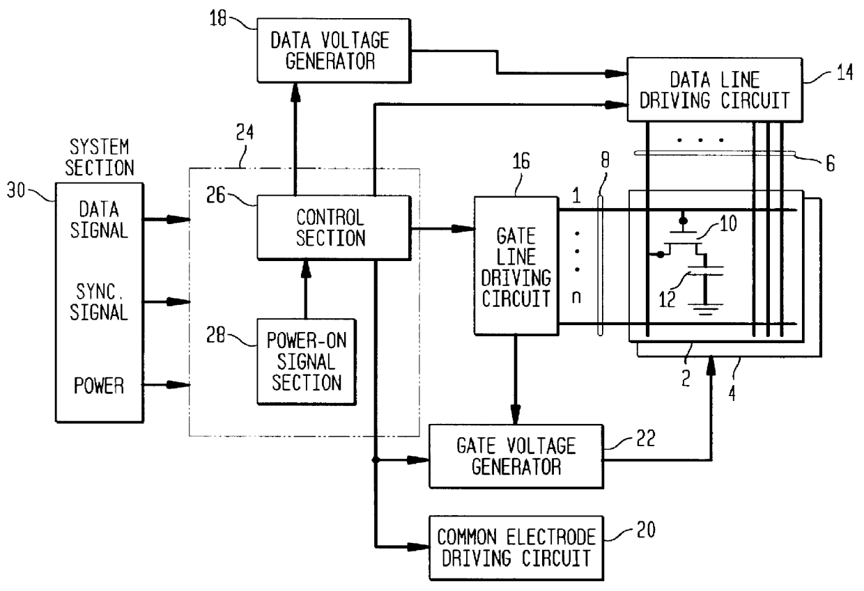
The configuration of a liquid crystal display device used in this embodiment will be briefly described with reference to FIG. 1. To begin with, an array substrate 2 and an opposed substrate 4, which are glass substrates, are opposed to each other at a given interval through a liquid crystal. Although not shown in the figure, a common electrode is formed over the almost entire surface of the opposed substrate 4. A common electrode driving circuit 20 is connected to the common electrode to apply a voltage to it.

A plurality of data lines 6 and a plurality of gate lines 8 that intersect the data lines 6 are formed on the array substrate 2. Pixel electrodes 12 are for...

second embodiment

With reference to FIGS. 5-7, a description will be made of a liquid crystal display device, its driving method, and its driving device according to the subject invention in which an OCB cell is transferred from a splay orientation state to a bend orientation state at a start of operation of the liquid crystal display device. This embodiment is directed to a driving method for effecting transfer to a bend orientation state in a short period at a start of display operation of a liquid crystal display device using an OCB cell by causing bend orientation in respective pixels by means of strong electric fields developing between a common electrode and storage capacitance electrodes (storage capacitance lines) of TFTs by applying voltage pulses between those electrodes and, at the same time, applying a voltage higher than that to generate an electric field necessary to maintain bend orientation between the common electrode and display electrodes (pixel electrodes).

FIG. 5 is a sectional vi...


PUM

PropertyMeasurementUnit
gate voltageaaaaaaaaaa
voltageaaaaaaaaaa

Abstract

The present invention relates to a driving method of a liquid crystal display device using an OCB (optically compensated birefringence) which realizes a wide view-field angle and high-speed response, and has an object of providing a driving method of a liquid crystal display device which method causes an OCB cell to transfer from a splay orientation state to a bend orientation state in short time. In a driving method of a liquid crystal display device using an OCB cell, gate on / off periods of a TFT are controlled at a start of a display operation, each pixel is caused to have bend orientation by a strong electric field that is generated between a gate electrode and a common electrode, and, at the same time, a voltage that is higher than that to generate an electric field necessary to maintain bend orientation is applied between a display electrode and the common electrode, to thereby effect transfer to bend orientation in short time.

Description

1. Technical FieldThe subject invention relates to a driving method of a liquid crystal display device and, more specifically, to a driving method of a liquid crystal display device using an OCB (optically compensated birefringence) technique which realizes a wide view-field angle and high-speed response.2. Prior ArtTwisted nematic (TN) cells, which at present are widely used in TFT color liquid crystal display devices (TFT / LCDs), have a small view-field angle, which results in a problem that when an LCD panel surface is viewed from an oblique direction, the contrast decreases and image inversion occurs. To solve this problem, i.e., to realize a wide view-field angle, various methods have been proposed. Among those methods is an orientation division method in which each pixel of an LCD is divided into two parts and orientation is effected in different directions in the two parts, and a method in which a pixel electrode is divided into a plurality of parts.Further, to accommodate a r...

Claims


Application Information

Patent Timeline
Patent Type & Authority Patents(United States)
IPC IPC(8): G09G3/36G02F1/13G02F1/139G02F1/137G02F1/133
CPCG09G3/3648G02F1/1395G09G2330/026G09G2310/0245G09G2310/063G09G2300/0491
Inventor NAKAMURA, HAJIMEKIMURA, YASUHIROKUNIAKI, SUEOKATAIRA, YOICHIUCHIDA, TATSUO
Owner AU OPTRONICS CORP
Why Eureka
Try Eureka