Shingle removing tool

a technology for removing tools and shingle, which is applied in the direction of roofs, lifting devices, construction, etc., can solve the problems of not having long extending tines, deteriorating shingles, and leakage, and achieves the effect of minimizing the necessity of a second step and minimizing the resistan

Inactive Publication Date: 2000-06-06
MISLICH JAY +1
View PDF15 Cites 12 Cited by
  • Summary
  • Abstract
  • Description
  • Claims
  • Application Information

AI Technical Summary

Benefits of technology

Thus, it is an object of the Applicant's device to provide a shingle removing tool constructed in such a way that it has forward extending tines which slip beneath the shingles with a minimum of resistance. It is a related object of the invention to use the elongated tines as a prying mechanism to lift the shingles from the roof.Another object of the invention is the object of providing a shingle removing tool that has rearwardly positioned teeth to engage nails remaining in the roof after the tines lift the shingles from the roof. Related to this object is the object of providing a plurality of rearwardly disposed teeth which remove nails remaining in the roof as the tool is pushed in a forward shingle removing direction which causes the teeth to engage any remaining roof nails.Yet another related object is the object of removing as many shingles and their fastening nails together. An advantage is that this minimizes the necessity of a second step of removing remaining nails by means of a separate tool.III.

Problems solved by technology

Over time, the shingles deteriorate and will leak.
This device does not have tines which are forced under the shingles in order to assist in removing them, nor does it have any mechanism to lift the nails from the roof by a tooth or claw mechanism.
A common problem with all of the prior art devices is that they do not provide long extending tines which are easy to slip under shingles and provide the leverage required to lift the shingles easily.
Furthermore, a problem with the prior devices is that the nail removing teeth are generally provided on the same initial cutting blade surface which is used to be pushed underneath the shingles.
This results in the teeth striking the nail heads and often snapping them off.
Furthermore, the teeth, as being a portion of the forward-most edge of the blade, quickly dull or themselves can be broken.

Method used


Image

  • Shingle removing tool
  • Shingle removing tool
  • Shingle removing tool

Examples


Embodiment Construction

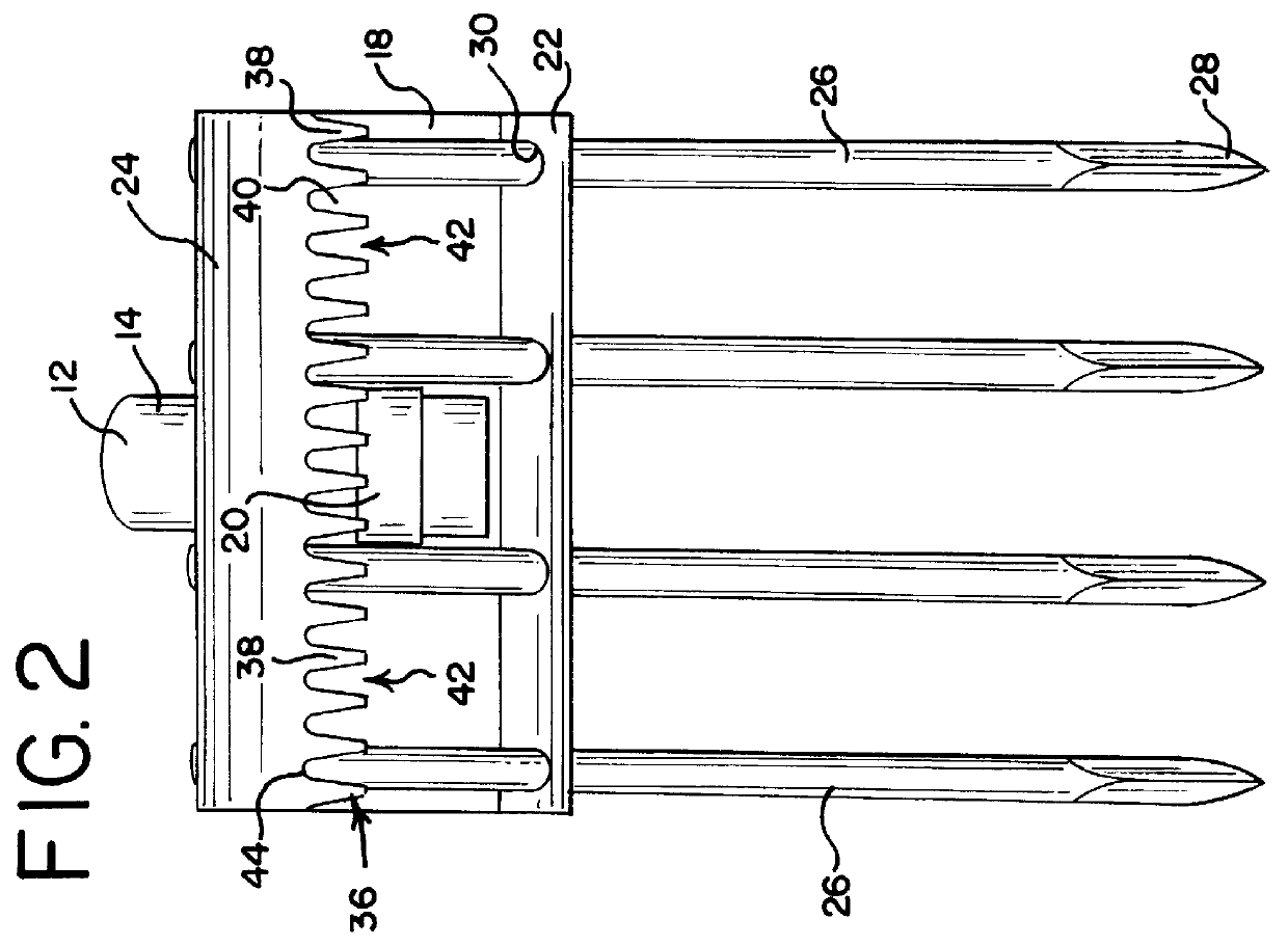
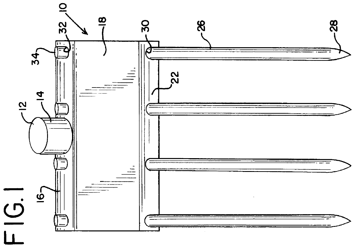
Turning first to FIG. 1, there is illustrated an inventive shingle removing tool 10 of the present invention. There is an elongated handle 12 which has its distal end grasped by the user. A forward end 14 is inserted into a tubular collar 20 which passes through a back wall 16 and of a base plate 18.

As seen in FIG. 2, which is the bottom view of the tool 10, the collar 20 passes through and is affixed to the underside of the base plate 18. Generally, the collar 20 will be welded to the base plate 18 but any other means by which the collar 20 can be firmly and fixedly attached to the base plate 18 will be apparent to those skilled in the art of metal forming and fastening. The forward end of the handle 14 is firmly received within the collar 20 by either a friction fit, or a fastener passing through the collar 20 and into the forward end 14. Furthermore, a combination of both a friction fit and fastener could also be utilized.

As can be seen in FIG. 3, the base plate 18 is formed in a...


PUM


Abstract

A tool for removing shingles and nails from a roof in which the tool has a base mounting plate which has a plurality of forwardly extending tines. The tines are adapted for pushing under the shingles. The tines pry the shingles loose from the roof. A plurality of forwardly extending teeth are positioned on the base plate below and rearward of the tines. The teeth remove nails remaining on the roof after the shingles are removed. Both the tines and teeth operate when the tool is pushed in a forwardly shingle removing direction.

Description

I. BACKGROUND AND SUMMARY OF THE INVENTIONThis invention relates to hand tools and more particularly to a hand tool used for removing shingles and nails from a roof.Houses are generally constructed having inclined roofs which are covered with a plurality of overlapping, horizontally aligned rows of shingles. The shingles may be made of asphalt or wood which are nailed to the roof. Generally, beginning with the bottom or lower-most edge of the roof, the shingles are nailed in place with successive layers or rows overlapping the top of the proceeding below-mounted row. The shingles are generally mounted to the roof by a plurality of nails.Over time, the shingles deteriorate and will leak. Thus, it is necessary to periodically remove the shingles in order to apply a new roof covering. In order to remove the shingles, it is necessary to pry up the shingles and nails. This is done in the reverse order as when the shingles were installed. At times, the shingles will pull the nails up with...

Claims


Application Information

Patent Timeline
Patent Type & Authority Patents(United States)
IPC IPC(8): E04D15/00
CPCE04D15/003
Inventor MISLICH, JAYMISLICH, JR., THOMAS
Owner MISLICH JAY
Why Eureka
Try Eureka