Broadband piezoelectric shunts for structural vibration control

a piezoelectric shunt and structural technology, applied in the direction of generator/motor, device details, device details, etc., can solve the problems of ineffective negative impedance converter of the prior art, inability to effectively cancel the impedance of pzt material, and lack of negative impedance converters to reconfigure and stabilize the shunt circui

a piezoelectric shunt and structural technology, applied in the direction of generator/motor, device details, device details, etc., can solve the problems of ineffective negative impedance converter of the prior art, inability to effectively cancel the impedance of pzt material, and lack of negative impedance converters to reconfigure and stabilize the shunt circui

US6075309AInactive Publication Date: 2000-06-13MCDONNELL DOUGLAS

Image

  • Broadband piezoelectric shunts for structural vibration control
  • Broadband piezoelectric shunts for structural vibration control
  • Broadband piezoelectric shunts for structural vibration control

Examples


Embodiment Construction

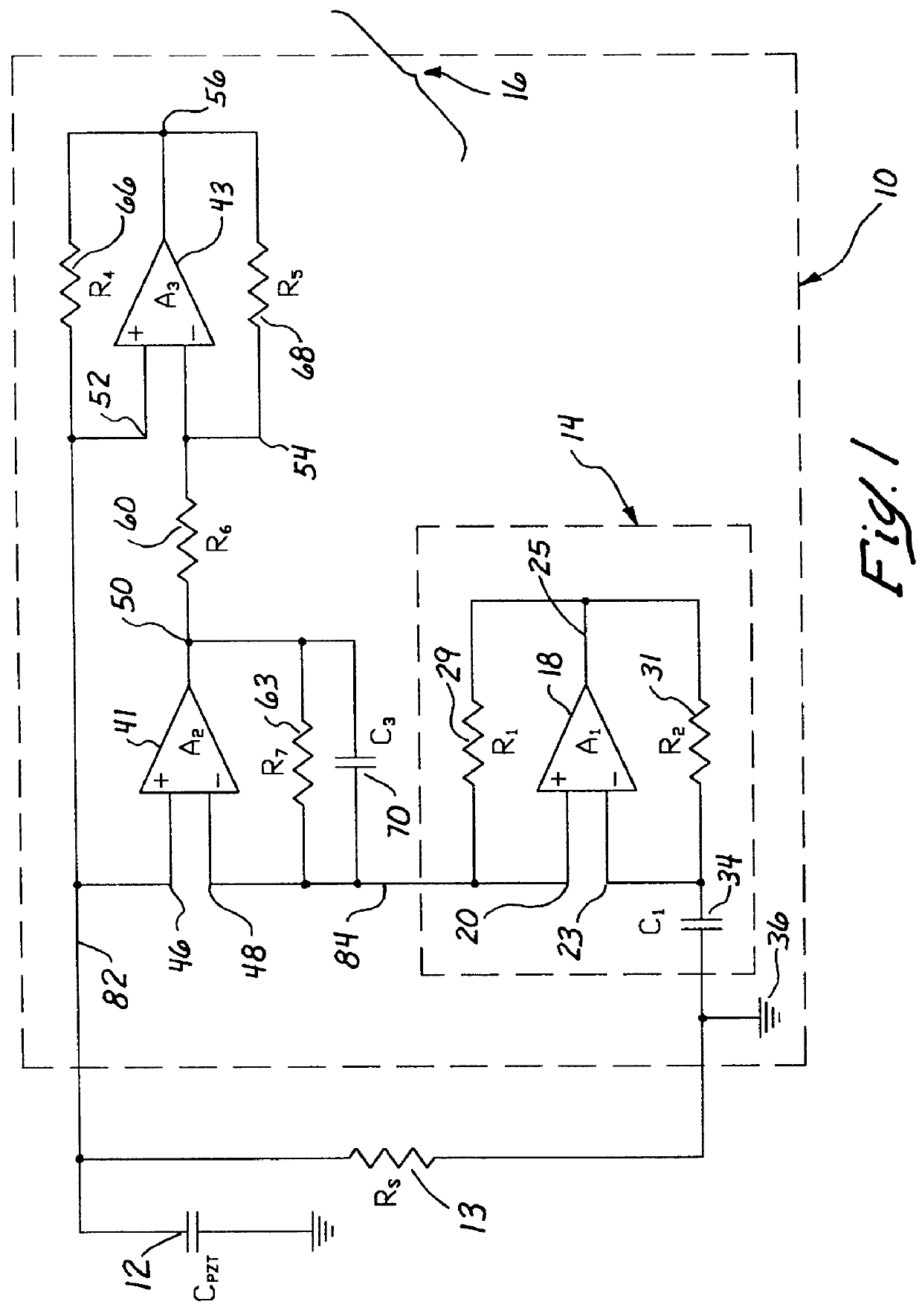
Referring more particularly to the drawings, a broadband piezoelectric shunt circuit 10 is illustrated in FIG. 1 coupled to an input load 12. The input load 12 preferably comprises a piezoelectric material, such as a thin patch of lead-zirconate-titanate. The broadband piezoelectric shunt circuit 10 comprises a negative impedance converter circuit 14, which is coupled to a Riordan-type circuit 16.

The negative impedance converter circuit 14 comprises an operational amplifier 18 having a positive terminal 20, a negative terminal 23, and an output terminal 25. A first resistor 29 is connected between the positive terminal 20 and the output terminal 25, and a second resistor 31 is connected between the negative terminal 23 and the output terminal 25. An impedance element 34 is connected between the negative terminal 23 and the ground 36. The impedance element 34 preferably comprises a capacitor, which is selected to have a capacitance equal to the capacitance of the input load 12. In al...


PUM


Abstract

A negative capacitance converter is used in combination with a buffer circuit to form an electrical shunt circuit. The negative capacitance converter and the buffer circuit, together, minimize or eliminate oscillations of a negative impedance generated by the electrical shunt circuit. Additionally, a specific configuration of the negative capacitance converter is used to provide optimum stability. The buffer circuit includes a Riordan-type circuit, with the negative capacitance converter being substituted for one of the impedance elements of the Riordan-type circuit. Resistors are used to replace the other impedance elements of the Riordan-type circuit. An additional capacitor is placed across one of the operational amplifiers of the Riordan-type circuit, in order to provide additional stability.

Description

1. Field of the InventionThe present invention relates generally to structural damping and vibration control devices and, more particularly, to passive piezoelectric shunt circuits.2. Description of Related ArtNegative impedance converters have been used in the prior art for reducing or neutralizing an impedance of an electrical circuit. One particular type of negative impedance converter is a negative capacitance converter. A negative capacitance converter generally comprises an operational amplifier having a first resistor connected between the positive input terminal of the operational amplifier and the output terminal of the operational amplifier, and a second resistor connected between the negative terminal of the operational amplifier and the output terminal of the operational amplifier. A capacitor is connected between the negative terminal of the operational amplifier and ground. The impedance of the capacitor is equal the 1 / j.omega.C. The input impedance of the negative imp...

Claims


Application Information

Patent Timeline
13 Jun 2000
Publication
US6075309A
IPC
H03H11/00; H03H11/48
CPC
H03H11/48; H03H11/10
Inventors
WU, SHU-YAU